ZnSe window double sided lapping is the planar surface preparation step that brings a cut zinc selenide blank into the flatness, parallelism, and surface finish range required by CO₂ laser windows, beam splitters, and protective covers. It is not the final polish — but every downstream parameter, from coating uniformity to transmitted wavefront, depends on what lapping leaves behind.
This guide covers the lapping workflow for ZnSe windows in the context of the full ZnSe CO₂ laser optics manufacturing chain: how the process differs from polishing, what parameters matter for flatness and TTV, where defects originate, and how to specify lapping for production runs.

What Is ZnSe Window Double Sided Lapping?
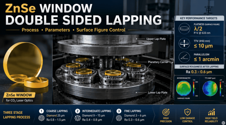
ZnSe window double sided lapping is the simultaneous abrasive removal of material from both faces of a zinc selenide window blank to bring the part to target thickness, parallelism, and pre-polish surface roughness. Both faces are worked at the same time on a double-sided lap machine, with the window held in a planetary carrier between two rotating laps charged with diamond slurry.
Two reasons “double sided” matters for ZnSe windows:
- Parallelism — single-side lapping accumulates wedge error; doing both faces in one fixturing pass keeps the two surfaces parallel to within a few arcseconds
- Stress balance — ZnSe is brittle and stress-sensitive; removing equal material from both faces avoids the bowing that single-side processing introduces
For CO₂ laser windows the typical output of lapping is:
- Thickness to within ±0.05 mm of nominal
- Parallelism better than 1 arcminute
- Surface roughness Ra 0.3–0.6 µm (depending on final abrasive grade)
- TTV (total thickness variation) of 5–15 µm on standard window diameters
These numbers are the starting point for polishing, not the finished window specification.
Why Double-Sided Lapping Matters for CO₂ ZnSe Windows
CO₂ laser windows have two surfaces, and the laser passes through both. Any wedge between the two faces deflects the beam. Any thickness variation across the aperture distorts the transmitted wavefront. Any subsurface damage from poor lapping carries through polishing and shows up as scatter in the finished part.
Three properties of ZnSe drive the lapping decisions:
| Property | Implication for Lapping |
|---|---|
| Knoop hardness ~120 kg/mm² | Soft material — over-pressure causes deep pitting and embedded grit |
| Brittle, low fracture toughness | Microcracks initiate easily; pressure and abrasive size must be controlled |
| Toxic selenium content | Slurry containment and waste handling are part of the process, not optional |
The fix is a low-pressure, controlled-abrasive double-sided lap — not just any planar grinding setup. Equipment built for general glass lapping often over-presses ZnSe and seeds defects that survive the entire downstream chain.
Process Steps and Typical Parameters
The lapping workflow runs in three abrasive stages, each driving down both roughness and subsurface damage:
Stage 1: Coarse Lapping (rough flatten)
Removes saw marks from the upstream cutting operation and establishes initial flatness. Uses bonded or loose diamond, typically 25 µm grit on cast iron laps.
| Parameter | Typical Range |
|---|---|
| Abrasive | Diamond, 25 µm |
| Lap material | Cast iron |
| Lap pressure | 0.5–1.5 kPa |
| Lap rotation | 30–60 rpm |
| Slurry vehicle | Water-based with corrosion inhibitor |
| Removal rate | 5–10 µm/min per face |
| Output Ra | 0.8–1.5 µm |
Stage 2: Intermediate Lapping (refine surface)
Refines the surface and reduces subsurface damage left by Stage 1. Diamond drops to 9–15 µm.
| Parameter | Typical Range |
|---|---|
| Abrasive | Diamond, 9–15 µm |
| Lap material | Cast iron or composite |
| Lap pressure | 0.3–0.8 kPa |
| Lap rotation | 30–50 rpm |
| Removal rate | 1–3 µm/min per face |
| Output Ra | 0.4–0.8 µm |
Stage 3: Fine Lapping (pre-polish prep)
Final lapping stage. Brings roughness into the pre-polish range and minimizes subsurface damage that polishing has to remove.
| Parameter | Typical Range |
|---|---|
| Abrasive | Diamond, 3–6 µm |
| Lap material | Composite or pitch-impregnated |
| Lap pressure | 0.2–0.5 kPa |
| Removal rate | 0.3–1 µm/min per face |
| Output Ra | 0.3–0.6 µm |
After Stage 3 the window goes to polishing — see zinc selenide optics polishing for the diamond-and-pitch progression that brings Ra below 10 nm RMS for laser-grade surfaces.
The upstream operation, cutting the ZnSe blank from a CVD ingot, is covered on the ZnSe lens cutting machine page. The whole chain from CVD blank to coated window is summarized on the ZnSe CO₂ laser optics manufacturing overview.
Surface Figure and TTV Specifications
The two metrics that determine whether a lapped ZnSe window is ready for polishing are surface figure (flatness) and TTV (parallelism).
| Specification | Typical Target | Why It Matters |
|---|---|---|
| Surface figure | λ/2 P-V at HeNe 633 nm | Sets the maximum figure error polishing has to correct |
| TTV (Φ50 mm window) | ≤ 10 µm | Wedge angle between the two faces deflects the beam |
| Parallelism | ≤ 1 arcmin | Same beam-deflection issue, expressed as angle |
| Surface roughness Ra | 0.3–0.6 µm | Sets the starting point for polishing removal |
| Subsurface damage depth | ≤ 3× peak abrasive size | Polishing has to remove all of it |
Material reference: II-VI / Coherent CVD ZnSe and Edmund Optics IR materials guide document the bulk material properties these targets are derived from.
Common Defects and How to Avoid Them
Why does TTV stay high after the final lapping stage?
Carrier wear or worn-out laps. The planetary carriers that hold windows during lapping wear over time, and once worn they no longer balance pressure across the lap face. The fix is scheduled carrier replacement on a defined cycle, not after defects appear.
Why are pits and scratches showing up after polishing?
Subsurface damage from over-aggressive lapping. ZnSe is soft. Too much pressure or too coarse an abrasive at Stage 3 leaves micro-pits that the polish cannot remove — they show up as scatter in the finished window. The fix is dropping pressure and adding a finer intermediate stage rather than trying to compensate at polish.
Why does the surface look hazy after lapping?
Embedded abrasive. When diamond particles get pressed into the soft ZnSe surface and stay there, the surface looks hazy and the next stage cannot pick them out. The fix is slurry concentration control plus mid-cycle ultrasonic cleaning between abrasive stages.
Why does the part chip at the edges?
Edge effect from unsupported workpiece edges in the carrier. The pressure distribution at the edge of a window is different from the center, and on a brittle material that difference becomes chipping. The fix is edge bevels on the blank before lapping starts, plus carriers sized to the part rather than oversized.
ZnSe Lapping vs Polishing: Where Each Fits in the Chain
Lapping and polishing both reduce surface roughness, but they do it differently and produce different surface states:
| Property | Lapping | Polishing |
|---|---|---|
| Mechanism | Mechanical abrasion | Mechanical + chemical |
| Output Ra | 0.3–0.6 µm | < 10 nm RMS |
| Surface figure | λ/2 P-V | λ/10 P-V or better |
| Subsurface damage | Present, controlled | Removed |
| Removal rate | High | Low |
| Function | Establish thickness, flatness, parallelism | Achieve laser-grade surface |
Lapping handles the bulk material removal and geometry control. Polishing handles the surface quality and final figure. A poorly lapped window cannot be saved by polishing — the polish removal rate is too slow to fix figure errors that should have been controlled at lapping.

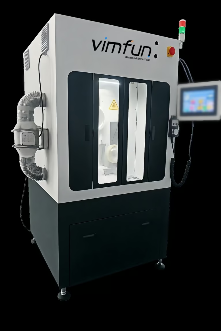
How Vimfun Supports ZnSe Window Manufacturers
Vimfun supplies the equipment that ZnSe window producers need across cutting, lapping, polishing, and coating preparation:
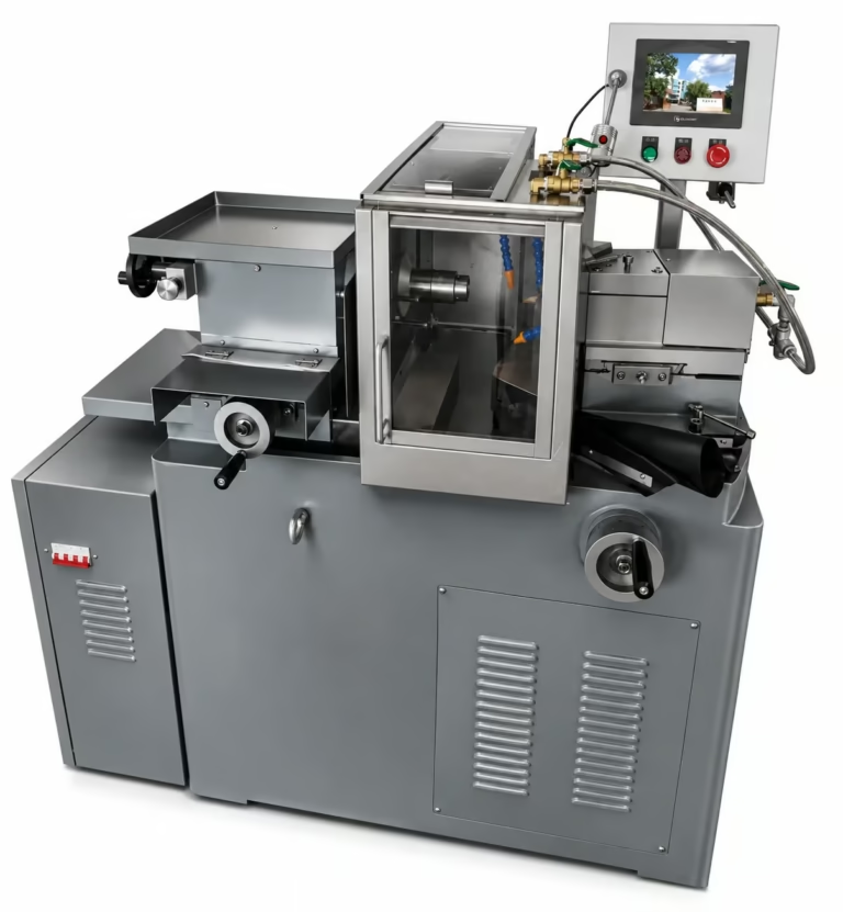
- Cutting — ZnSe lens cutting machine configured for brittle II-VI materials with low-tension wire feed and contamination-controlled coolant
- Polishing — zinc selenide optics polishing systems matched to laser-grade surface specifications
- Process integration — equipment shares mechanical platforms with our infrared optics manufacturing equipment line, so a ZnSe production cell scales to Ge, ZnS, CaF₂, and Si without re-tooling
If you are building a new ZnSe window line, scaling capacity for CO₂ laser cutting head production, or replacing equipment that cannot hold TTV within 10 µm on Φ50 mm parts, send us your target geometry, throughput, and surface specification. We will return a configured proposal within 3 business days, including cycle time estimates and yield projections based on similar installations.