STEP 02 / OPTICAL MANUFACTURING

Optical Lens Grinding Machine

From manual generating to CNC production: match your lens geometry, diameter and loading method to the right machine.

Ø4–120 mmSpherical family coverage
R2 to flatModel-dependent curvature
Manual → CNCSix production configurations
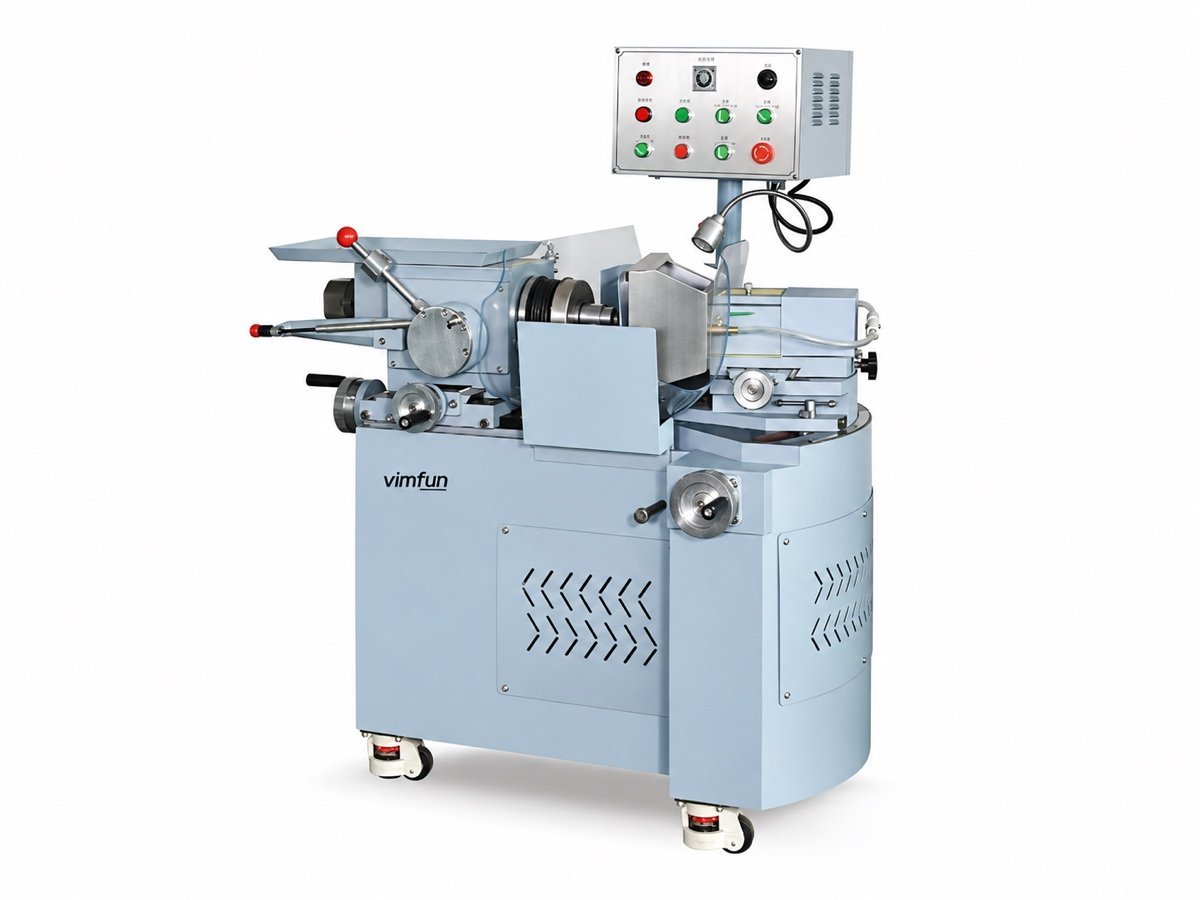
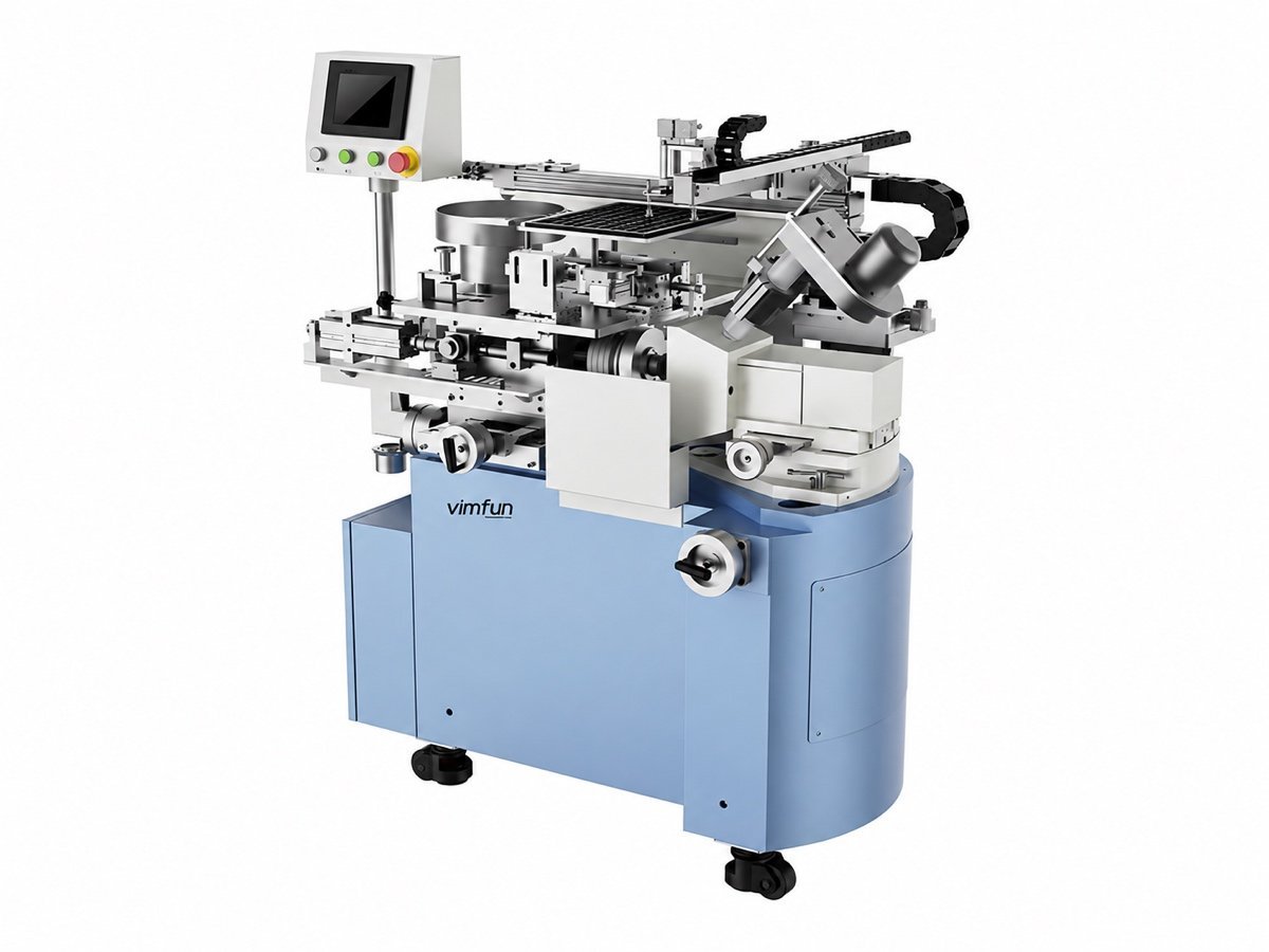
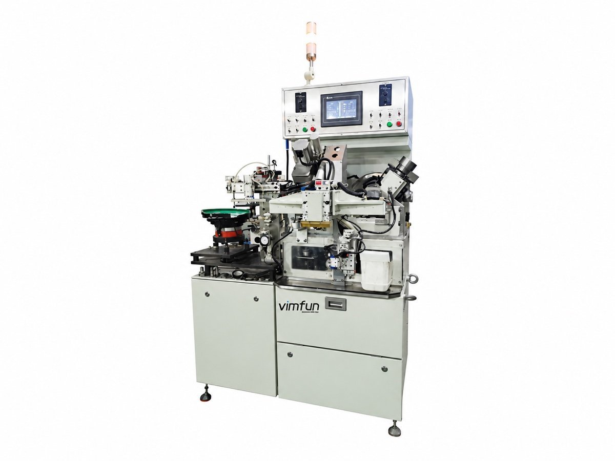
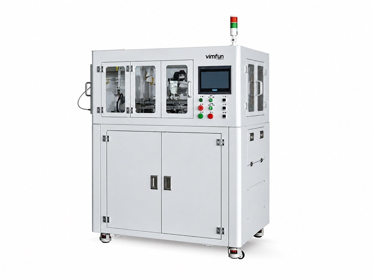
Auto-SG-50 optical lens grinding machine with enclosed machining chamber
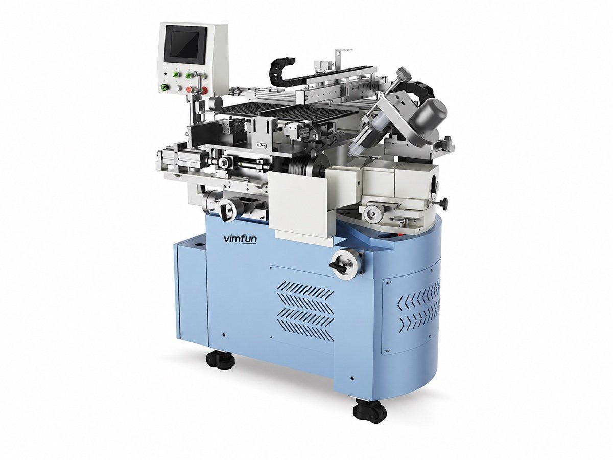
Auto-SG-50CNC generating with in-process sagitta measurement
01 / DEFINE THE TASK

Choose an optical lens grinding machine around the workpiece

Generating gives a cut blank its next usable geometry: a spherical radius, a cylindrical surface, or a machined bore. The part then moves to fine grinding and polishing with a defined finishing allowance. An optical lens grinding machine therefore needs to be selected for both the incoming blank and the condition required by the next operation.

Vimfun’s range includes manually loaded generators, vibratory and tray-fed machines, CNC generating with measurement feedback, a vertical twin-spindle configuration, and dedicated cylindrical and bore machines. Start with the shape you need to produce. Then compare handling, batch size and changeover. The same diameter on a quotation does not mean two machines perform the same job.

For buyers comparing a lens grinding machine or an optical lens grinder, the tables below separate three decisions: surface geometry, workpiece envelope and production method. Detailed specifications remain on each product page. These machines serve precision optical-component manufacturing; they are not dispensing-laboratory systems for fitting prescription lenses.

02 / PRODUCTION METHOD

Which loading method fits your production?

Select the optical lens grinding machine loading arrangement around the way blanks arrive and finished parts leave. Automation is most useful when it removes a defined handling task. It also changes tray preparation, replenishment and changeover work.

Compare loading and production configurations
Production methodModelsHow parts moveSelection question
Manual loadingSG-80 / SG-120An operator loads each blank; generating follows the setup.Frequent changes of diameter, fixture or part family; direct access during setup.
Vibratory bowlAuto-SG-20VLoose blanks are fed automatically for repeated small-lens work.Check feed orientation, thickness variation and how finished parts are collected.
Tray in / tray outAuto-SG-80TSeparate parallel trays hold blanks and finished parts.Ordered batches and defined part positions between operations.
Bowl in / tray outAuto-SG-50VTVibratory feeding is combined with X/Y placement into a finished tray.Loose incoming blanks need to leave in an organized pattern.
CNC with feedbackAuto-SG-50 / Auto-SG-80CStaged servo infeed, sagitta measurement and automatic compensation.Repeated spherical work where process adjustment and wheel condition need closer control.
Vertical twin spindleAuto-SG-20WTwo vertical spindles, automatic loading and both-face processing.Small lenses requiring a coordinated face sequence and chamfering.

For a mixed workload, manual loading can make fixture changes straightforward. For a repeated small part, a bowl may remove repetitive loading. Trays preserve known part positions and can simplify transfer to another station. Evaluate the whole batch, including loading interruptions and inspection, rather than comparing only the programmed grinding cycle.

03 / GEOMETRY & WORKING RANGE

Compare diameter and curvature together

The spherical range spans Ø4–120 mm across different models. R2 capability belongs to the Auto-SG-20V; it is not a specification for every generator. Compare diameter and radius on the same row, then check blank thickness, the fixture and tool access.

Model-specific diameter and curvature ranges
ModelWorkpiece or travel referenceCurvature referenceGeometry / qualification
SG-80Up to Ø80 mmConfirm against drawingManual spherical / flat generating
SG-120Up to Ø120 mmConfirm against drawingLarger manual spherical generating
Auto-SG-20VØ4–20 mmR2 to flatSmall-lens automatic generating
Auto-SG-80TØ10–80 mmR5 to flatTray-fed generating
Auto-SG-50VTØ6–50 mmR5 to flatBowl-in, tray-out generating
Auto-SG-50Ø10–55 mmR5 to flatCNC generating
Auto-SG-80CØ5–80 mmR5 to flatCNC size variant
Auto-SG-20WØ5–20 mm±R2.5 to flatVertical twin-spindle generating
CG-140X/Y travel: 140 × 140 mmDrawing-dependentCylindrical surfaces; travel is not finished-part size
BG-50Maximum processing range: 50 mmNot a spherical-radius specificationBores, slots, outside surfaces and flats

For an optical lens grinding machine, a usable working envelope is more than the largest number in a brochure. A steep radius, a thin edge or a restrictive fixture can change tool access. Send the drawing and incoming blank dimensions together. CG-140 axis travel and BG-50 processing range are listed separately because neither is a stated maximum spherical-lens diameter.

04 / MACHINE FAMILIES

Explore the machine families

SG-80
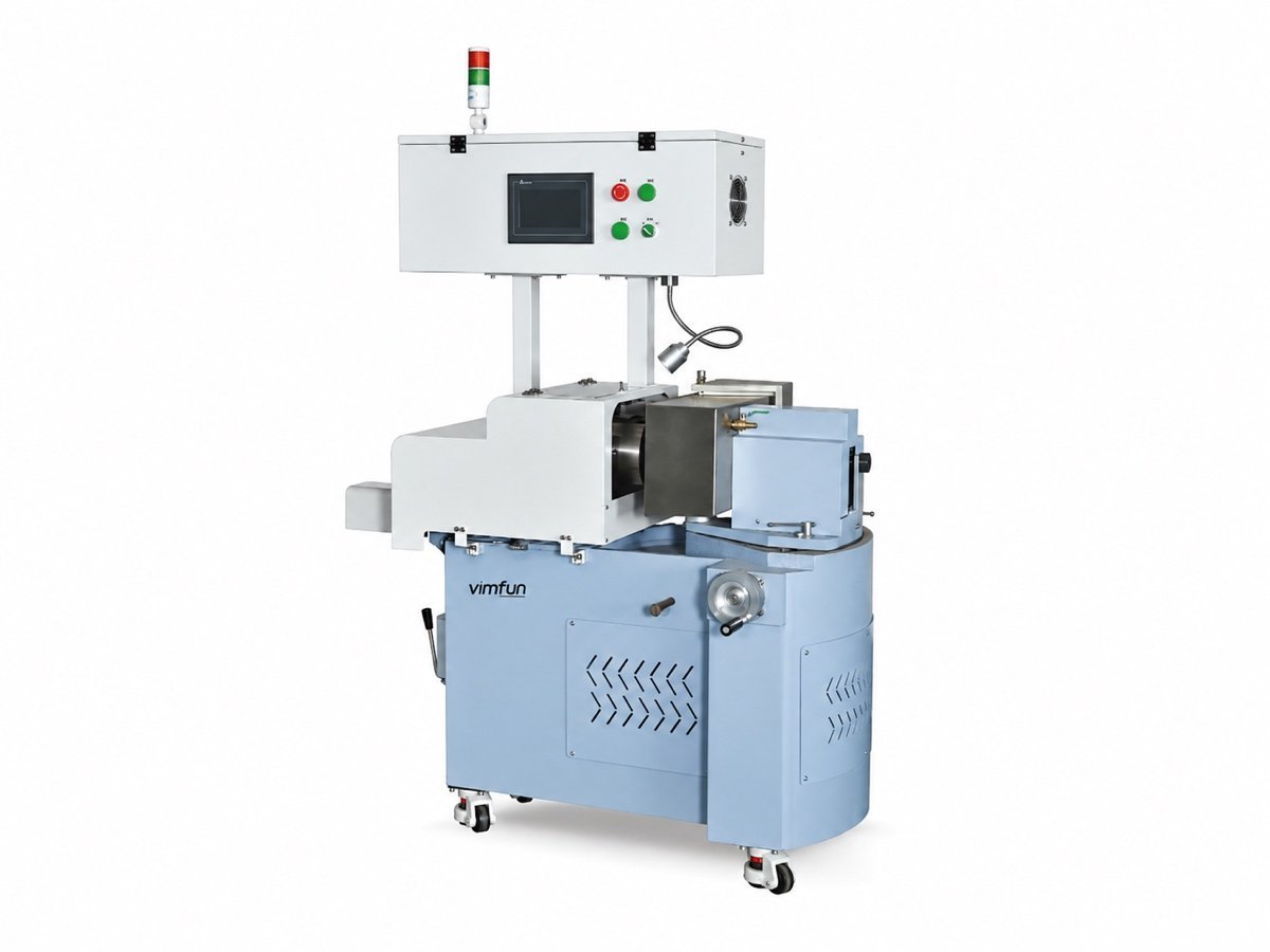
SG-80 — Manual spherical generating

Manual spherical generating

SG-80 is the starting point for operator-loaded spherical and flat work up to Ø80 mm. Its wheel-speed references are 8,000/11,000 rpm. Select it when access to the fixture and straightforward changes between part families matter more than automated loading.

View machine specifications ↗
SG-120
SG-120 — Larger lenses, internal-jet cooling

Larger lenses, internal-jet cooling

SG-120 extends manual generating to Ø120 mm. A more powerful spindle arrangement and internal-jet cooling distinguish it from the smaller model. Review the blank mass, fixture support and cooling access when moving to a larger lens.

View machine specifications ↗
Auto-SG-20V
Auto-SG-20V — Loose blanks, automatic feeding

Loose blanks, automatic feeding

Auto-SG-20V covers Ø4–20 mm and R2 to flat. Bowl feeding, face identification and automatic flipping support repeated small-lens work. Vacuum detection helps prevent an empty processing cycle; pressure and damping adjustments support control of the part during machining.

View machine specifications ↗
Auto-SG-80T
Auto-SG-80T — Keep each batch in a tray

Keep each batch in a tray

Auto-SG-80T covers Ø10–80 mm and R5 to flat. The blank and finished trays sit in parallel, with X/Y handling between them. Check the proposed tray layout against part thickness, orientation and the transfer requirements of the following station.

View machine specifications ↗
Auto-SG-50VT
Auto-SG-50VT — Combine loose feeding with organized output

Combine loose feeding with organized output

Auto-SG-50VT covers Ø6–50 mm and R5 to flat. It combines a vibratory bowl for incoming blanks with X/Y placement of finished parts. This configuration fits a specific hand-off: incoming parts are loose, but the next operation needs ordered trays.

View machine specifications ↗
Auto-SG-50 / Auto-SG-80C
Auto-SG-50 / Auto-SG-80C — CNC control with process feedback

CNC control with process feedback

Auto-SG-50 and Auto-SG-80C share the CNC generating concept but have different diameter ranges: Ø10–55 mm and Ø5–80 mm. Staged servo infeed, sagitta feedback, automatic flipping and wheel dressing help manage repeated spherical production.

View machine specifications ↗
Auto-SG-20W
Auto-SG-20W — Small lenses, two vertical spindles

Small lenses, two vertical spindles

Auto-SG-20W processes Ø5–20 mm lenses, with a ±R2.5-to-flat curvature reference. Both-face processing and a chamfering device are part of its documented configuration. The two spindle functions are independent; select the setup against the complete two-face drawing.

View machine specifications ↗
CG-140
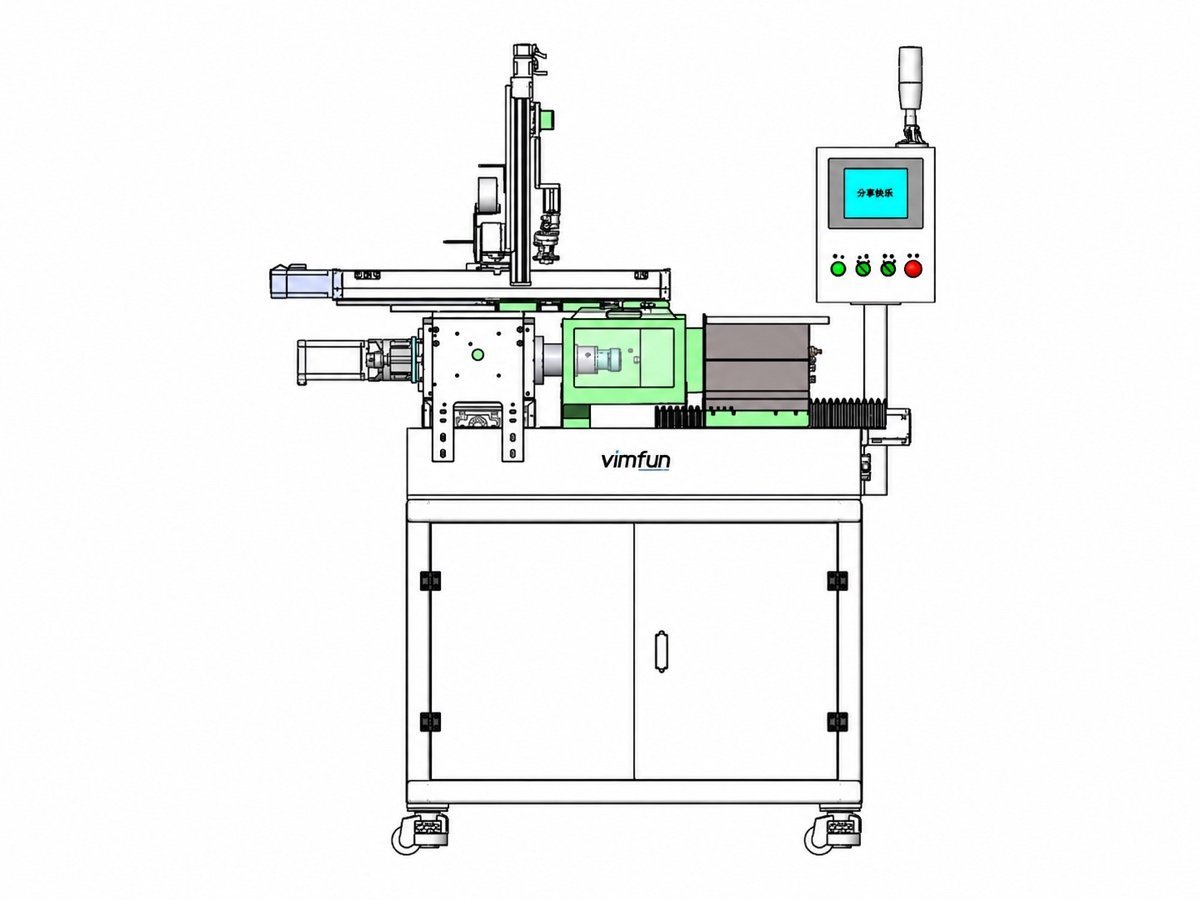
CG-140 — A separate route for cylindrical optics

A separate route for cylindrical optics

CG-140 machines glass cylindrical parts using X/Y servo motion and a swivelling grinding spindle. Convex and concave cylindrical surfaces are covered; a zero-degree spindle setting can produce a flat. Loading is manual and the grinding cycle is automatic.

View machine specifications ↗
BG-50
BG-50 — Bores and related features

Bores and related features

BG-50 uses a high-speed electric spindle, up to 30,000 rpm, with an ER32 collet. It machines round and oblong holes and also supports outside and flat features. Automatic handling follows fixture setup. Confirm the drawing against the stated 50 mm processing range.

View machine specifications ↗
05 / CONTROL THE GENERATING OPERATION

What does CNC feedback actually control?

On the CNC optical lens grinding machine family, automation combines handling with control of the generating operation. Auto-SG-50 and Auto-SG-80C provide the four functions below. These functions are model-specific; they should not be assumed for a manual generator or a cylindrical machine.

01

Load & identify

Position the blank and identify its face.

02

Generate

Apply independently set servo-infeed stages.

03

Measure & correct

Use sagitta feedback for compensation.

04

Flip & maintain

Process the next face; dress the wheel at configured intervals.

Five-stage servo infeed

Each stage has its own travel and speed settings. The operator can separate material removal into stages instead of applying one feed throughout the operation. Set the sequence for the blank, abrasive and required remaining stock, then assess the result on representative samples.

Sagitta measurement and compensation

The on-machine gauge measures sagitta and supports automatic compensation. Sagitta describes the height of a spherical surface over a defined span. Agree that span and the reference condition before comparing readings with the drawing; a compensation value alone is not a complete optical acceptance report.

Face recognition and automatic flipping

The machine identifies the two faces and turns the part for the next operation. This reduces a repeated handling step. During selection, check the starting face, reference surface and part orientation against the actual lens geometry and loading arrangement.

Automatic wheel dressing

Dressing intervals and counts can be configured to maintain the wheel’s working condition. Include dressing, replenishment and measurement time when comparing output. A useful trial records accepted parts over a batch, not only the quickest single grinding cycle.

06 / PROCESS HAND-OFF

From a cut blank to a surface ready for finishing

A spherical optical lens grinding machine establishes a radius through the relationship between the cup wheel and spindle angle. The Auto-SG-50 specification gives sin θ = d / (2R), where d is the tool diameter used in the setup geometry and R is the target radius. The tooling and angle must be selected together.

Generating removes stock efficiently, but the surface still needs fine grinding and polishing. Define the allowance to be left, the center-thickness condition and acceptable edge damage before machining. Too much remaining stock increases finishing work; too little may prevent the next process from removing the damaged layer.

A useful process review connects cutting, generating and finishing. Show the application team how the blank was made and which operation follows. A quoted lens grinding machine should leave a part that the finishing station can accept consistently. Treat cylindrical surfaces and bores separately: the spherical cup-wheel relationship is not a general formula for CG-140 or BG-50.

Which materials and shapes are covered?

Match an optical lens grinding machine to a documented model and material, not only to a family-level headline. The following examples identify candidates whose supplied material lists support the application. For models specified simply for optical lenses, send the material and drawing for evaluation.

Material selection starts with the named model
MaterialDocumented model examplesWhat to supply
Optical glassSG-80; Auto-SG-50 / Auto-SG-80C; BG-50Give the glass grade, blank condition and required surface. CG-140 is the dedicated cylindrical option for glass parts.
SapphireSG-80; Auto-SG-50 / Auto-SG-80C; BG-50Include crystal orientation where specified, finished geometry and the edge condition needed by the next operation.
Technical / optical ceramicsSG-80; Auto-SG-50 / Auto-SG-80C; BG-50Identify composition and grade. Trial the chosen tooling and process on representative blanks.
Quartz / crystalBG-50 lists quartz and crystal; SG-80 lists crystalName the material precisely. Select other machine configurations through application review rather than transferring this material list.

Crystalline quartz and fused silica should be identified separately on an enquiry. Crystran’s crystal quartz data explains that distinction. Its sapphire data provides background on sapphire’s directional properties. These references help describe the incoming material; machine selection still depends on the proposed geometry, tooling and trial.

Working with infrared optics?

For an infrared optical lens grinding machine enquiry, also compare the existing G-100 and G-250 range. These are separate product families from the SG generators above. Their size references are Ø10–100 mm and Ø80–250 mm respectively; consult the corresponding product page for material and configuration details.

What should the sample trial prove?

Use a sample trial to check the optical lens grinding machine against your drawing and the next production step. Vimfun offers free sample machining for grinding applications. Send representative blanks and agree the sample quantity, trial scope and shipping arrangements with the team.

Before the trial, record the incoming size, material grade and surfaces already completed. Agree the output checks: radius, center thickness, relevant features, edge condition and remaining finishing stock. Use the same reference surfaces and measurement method when comparing the trial report with your own inspection.

For repeated production, include several consecutive parts and record setup, loading, dressing and inspection activities. This makes the comparison more useful than a single good component. A spindle-runout number describes a machine characteristic; it should not be substituted for the finished-part measurements required on the drawing.

What changes the equipment quotation?

An optical lens grinding machine proposal depends on geometry, workpiece range, loading method and control functions. Tooling, fixtures, trays, measurement options and installation scope also affect the quotation. Compare those items against the same production task before comparing totals.

For replacement equipment, describe the current bottleneck: repeated manual adjustment, long changeovers, handling damage or an unbalanced process. For a new cell, define the intended sequence and part mix. The application team can then explain which configuration is necessary and which capability would add complexity without helping the job.

Vimfun’s documented support includes a 12-month warranty from final acceptance and continuing spare-parts support. Confirm the service scope, commissioning plan and training arrangements in the quotation. Acceptance should identify both the machine checks and the agreed output measurements on your sample parts.

Questions before selecting a generator

How do I choose between manual and automatic loading?

Start with the part mix and how blanks arrive. Manual loading suits frequent setup access; bowl feeding handles repeated small parts; trays preserve defined positions. Compare a complete batch, including preparation and changeover, rather than using the single-part machining cycle as the only measure.

Can one optical lens grinding machine cover the entire Ø4–120 mm range?

No. That is the coverage of the spherical machine family. Auto-SG-20V starts at Ø4 mm, while SG-120 extends to Ø120 mm. Diameter and curvature must be checked together for the selected model, followed by fixture and tool-access review.

Does generating produce a polished optical surface?

Generating establishes geometry and leaves stock for subsequent finishing. Fine grinding and polishing refine that surface. Agree the outgoing thickness, radius and finishing allowance so the next process receives a consistent part.

Can the same setup make spherical and cylindrical lenses?

The machine motions and workholding differ. SG models address spherical generating, while CG-140 is the dedicated cylindrical machine. Identify the actual surface geometry before comparing automation features or workpiece size.

What should I send for an optical lens grinding machine proposal?

Send the finished drawing, material grade, incoming blank dimensions, batch quantity and required output. Include the previous and next operations, existing trays or fixtures, and the measurement method used for acceptance. A photograph of the current setup can help explain handling constraints.

APPLICATION REVIEW / VIMFUN

Send one drawing. Start with the right process.

Tell us your material, blank size, finished geometry and production quantity. We will compare the suitable optical lens grinding machine configurations and define the next step for a sample trial.

Discuss your grinding application
Scroll to Top