Germanium IR optics manufacturing is the end-to-end process of transforming raw germanium crystal ingots into precision infrared optical components — lenses, windows, prisms, and filters — that transmit wavelengths from 1.8 to 23 μm for thermal imaging, FLIR systems, and spectroscopy applications. Unlike visible-light glass optics, germanium IR optics manufacturing requires specialized equipment and process controls at every stage because germanium’s unique combination of high refractive index (n = 4.003 at 11 μm), extreme brittleness, and sensitivity to subsurface damage demands cutting, grinding, and polishing techniques specifically engineered for this material.
This guide covers the complete germanium IR optics manufacturing workflow, the critical quality parameters at each stage, and the equipment configuration that determines whether your finished optics meet the surface quality and transmission specifications required by thermal imaging OEMs.

What Is Germanium IR Optics Manufacturing?
Germanium IR optics manufacturing encompasses all processing steps between a raw germanium crystal boule and a coated, inspected optical component ready for integration into an infrared system. The process chain includes: ingot cropping, blank slicing, curve generating (for lenses), grinding, lapping, polishing, coating, and final metrology.
Germanium (Ge) is the preferred material for 8–12 μm long-wave infrared (LWIR) optics due to its high refractive index of 4.003 at 11 μm — the highest among commonly used IR materials. According to Knight Optical, this high index enables lens designs with fewer elements and shorter optical paths compared to zinc selenide or chalcogenide alternatives, reducing system size and weight in thermal cameras and FLIR modules.
Key material properties that define germanium IR optics manufacturing requirements:
| Property | Value | Manufacturing Implication |
|---|---|---|
| Transmission Range | 1.8–23 μm | Suitable for MWIR and LWIR bands |
| Refractive Index | 4.003 @ 11 μm | Enables compact lens designs |
| Density | 5.33 g/cm³ | Heavy — requires stable fixturing |
| Knoop Hardness | 780 | Hard but brittle — subsurface damage risk |
| Melting Point | 937°C | Allows high-temp processing |
| Thermal Runaway | Above ~100°C use temp | Transmission drops — limits operating environment |
Germanium IR Optics Manufacturing: Stage-by-Stage Process
The germanium IR optics manufacturing process follows a defined sequence where each stage’s output quality directly constrains what the next stage can achieve. Skipping or rushing early stages creates subsurface damage that no amount of final polishing can remove.
Stage 1: Crystal Preparation and Blank Cutting
The process begins with single-crystal germanium ingots grown via the Czochralski (CZ) method. Ingots are first cropped to remove the seed and tail sections, then sliced into blanks matching the target optic’s diameter and thickness with appropriate stock allowance for subsequent grinding.
For precision IR optics, blank cutting with a germanium lens cutting machine using diamond wire technology is critical. Diamond wire cutting produces kerf widths of 0.25–0.35 mm — roughly half the material loss of traditional ID blade sawing — and introduces minimal subsurface damage compared to abrasive blade methods. With germanium raw material costing $1,800–2,400/kg, every fraction of a millimeter of kerf loss translates directly to material cost savings.
Blank cutting specifications for typical germanium IR optics:
| Optic Type | Blank Diameter | Blank Thickness | Cutting Method | Kerf Width |
|---|---|---|---|---|
| FLIR Lens (25 mm) | 28–30 mm | 5–8 mm | Diamond wire | 0.25–0.30 mm |
| Thermal Window (50 mm) | 54–56 mm | 3–5 mm | Diamond wire | 0.28–0.35 mm |
| ATR Prism | Custom | 8–15 mm | Diamond wire | 0.30–0.35 mm |
| Large Format Lens (100 mm+) | 105–110 mm | 10–20 mm | Diamond wire / ID saw | 0.35–0.50 mm |
Proper blank preparation at this stage directly supports germanium lens blank cutting efficiency — achieving consistent thickness uniformity (TTV 8–15 μm for Φ50 mm blanks) from the saw reduces the stock removal required during subsequent grinding. The as-cut surface roughness from diamond wire sawing typically falls in the Ra 0.6–1.2 μm range, which provides a suitable starting point for subsequent grinding without excessive stock removal.

Stage 2: Curve Generation and Rough Grinding
For flat optics (windows, filters), blanks proceed directly to lapping. For lenses, CNC curve generators produce the spherical or aspheric surfaces using diamond-bonded tools.
Curve generation establishes the optical surface geometry within 5–10 μm of the final radius of curvature. The process introduces a subsurface damage layer of 10–30 μm depth that must be removed during subsequent fine grinding and polishing.
Critical parameters during curve generation:
- Spindle speed: 2,000–4,000 RPM depending on blank diameter
- Diamond tool grain size: 20–40 μm for rough generation, 5–10 μm for fine generation
- Coolant: Water-based, continuous flow to prevent thermal damage
- Form accuracy target: < 5 μm departure from nominal radius
Stage 3: Fine Grinding and Lapping
Fine grinding removes the subsurface damage from curve generation while bringing the surface form closer to final specification. For flat germanium optics, double-sided lapping using a germanium lens grinding equipment setup achieves parallelism and flatness simultaneously.
The lapping sequence typically progresses through 3–4 grit steps:
| Step | Abrasive | Grain Size | Surface Roughness After | Subsurface Damage |
|---|---|---|---|---|
| Rough Lap | Al₂O₃ | 20 μm | Ra 1.0–1.5 μm | 15–20 μm |
| Medium Lap | Al₂O₃ | 9 μm | Ra 0.4–0.6 μm | 8–12 μm |
| Fine Lap | Al₂O₃ | 3 μm | Ra 0.15–0.25 μm | 3–5 μm |
| Pre-polish Lap | CeO₂ | 1 μm | Ra 0.05–0.10 μm | < 2 μm |
For window-type optics requiring tight parallelism, double-sided lapping processes both surfaces simultaneously, achieving TTV < 5 μm across 50 mm diameter parts.
Stage 4: Polishing
Polishing is the final material removal step in germanium IR optics manufacturing, responsible for achieving the surface roughness and form accuracy that directly determine optical transmission and wavefront performance.
A dedicated germanium optics polishing machine configuration uses polyurethane or pitch polishing pads with colloidal silica or diamond slurry to achieve:
- Surface roughness: Ra ≤ 0.01 μm (10 nm) for precision optics
- Form accuracy: < 0.5 fringes (λ/4 at 633 nm) for standard; < 0.1 fringes for high-precision
- Scratch-dig: 40-20 for standard; 20-10 for high-performance applications
- Surface figure: < 0.25 waves for FLIR lens elements
The polishing process must balance removal rate against surface quality. Excessive pressure or speed generates heat that can alter the germanium surface chemistry, creating absorption sites that reduce IR transmission.
Stage 5: Coating
Uncoated germanium reflects approximately 36% of incident infrared radiation per surface due to its high refractive index. Anti-reflection (AR) coatings are essential for practical germanium IR optics manufacturing — without coating, a simple germanium lens would transmit only about 41% of incoming radiation.
Standard coating options for germanium IR optics:
| Coating Type | Transmission | Band | Durability | Typical Application |
|---|---|---|---|---|
| Single-layer AR | > 85% | 8–12 μm | Moderate | Laboratory optics |
| Multi-layer AR | > 95% | 3–12 μm | Good | Industrial thermal cameras |
| DLC (Diamond-Like Carbon) | > 90% | 7–14 μm | Excellent | Military / outdoor FLIR |
| Hard Carbon AR | > 92% | 8–12 μm | Excellent | Harsh environment optics |
DLC coatings are particularly important for germanium optics used in exposed environments because germanium is relatively soft compared to visible-light glasses and scratches easily without protection.
Quality Control in Germanium IR Optics Manufacturing
Every stage of germanium IR optics manufacturing requires in-process measurement. Waiting until final inspection to discover defects wastes material and processing time on parts that should have been rejected earlier.
Critical inspection points:
- After blank cutting: Thickness uniformity (TTV), edge chip inspection, crystal orientation verification
- After curve generation: Radius of curvature measurement, subsurface damage assessment
- After lapping: Flatness / form accuracy, parallelism (for windows), surface roughness
- After polishing: Interferometric surface figure, scatter measurement, scratch-dig inspection
- After coating: Spectral transmission measurement, coating adhesion test, environmental cycling
According to Lattice Materials, germanium IR optics manufacturing facilities typically maintain ISO 9001:2015 certification with full traceability from crystal source through finished optic — a requirement for defense and aerospace thermal imaging programs.
Germanium IR Optics Manufacturing Equipment Configuration
The equipment chain for germanium IR optics manufacturing must be matched for germanium’s specific material properties. Standard glass processing equipment often lacks the rigidity, speed control, and coolant management required for germanium’s combination of high density, brittleness, and thermal sensitivity.
A complete germanium IR optics manufacturing line typically includes:
- Diamond wire saw for blank cutting — matched to germanium hardness and fracture characteristics
- CNC curve generator for lens surface creation — with diamond tooling rated for Knoop 780 hardness
- Double-sided lapping machine for flat optics — with load control for germanium’s density (5.33 g/cm³)
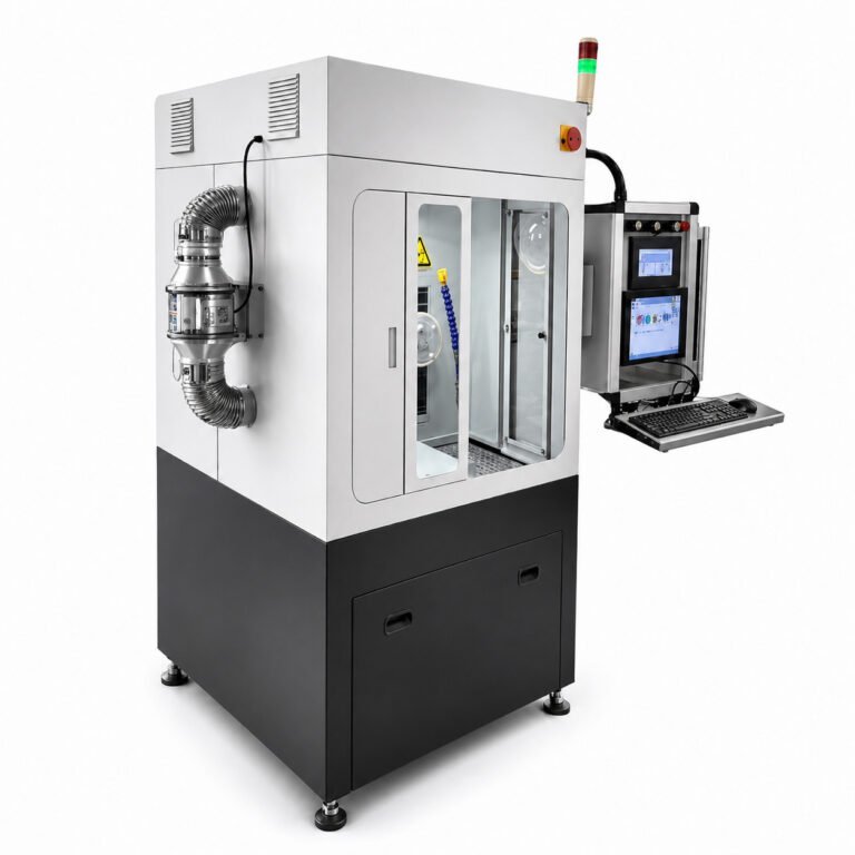
- CNC polishing machine — with temperature monitoring to prevent thermal runaway during processing
- Thin-film coating system — configured for germanium’s IR band AR coating recipes
- Interferometer + spectrophotometer — for final surface figure and transmission verification
The Pillar page on infrared optics manufacturing equipment provides detailed specifications for each equipment category in a complete germanium processing facility.
How to Evaluate a Germanium IR Optics Manufacturing Partner
When sourcing germanium IR optics from a contract manufacturer, verify these capabilities:
- Crystal source traceability: Can they confirm single-crystal orientation and purity grade?
- Subsurface damage control: Do they measure SSD at each processing stage, or only at final inspection?
- Coating capability: In-house coating versus outsourced — affects lead time and quality control continuity
- Metrology range: Can they measure form accuracy at the operating wavelength (10.6 μm), not just visible (633 nm)?
- Environmental testing: Do they perform thermal cycling and humidity testing on coated optics?
For volume production of germanium thermal imaging lenses, request process capability data (Cpk values) for your critical specifications — not just a single inspection report from a cherry-picked sample.
Need equipment for in-house germanium IR optics manufacturing? Contact our engineering team → for a consultation on cutting, grinding, lapping, and polishing equipment configured specifically for germanium optics production.