
Crystal Polishing Machine
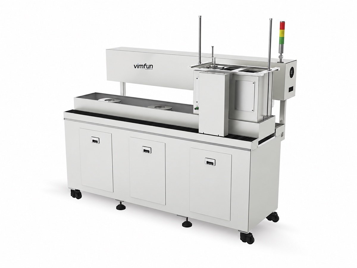
On optical crystals, most scrap is made before the plate ever turns. A crystal polishing machine is only as good as the fixture under the parts and the pressure it lets each one see.
Why optical crystals fail in the fixture, not on the plate
Quartz crystal, sapphire and the fluoride crystals are hard, brittle and mostly single-crystal. Three things decide the result, and only one of them is the polishing plate.
Fixturing stress
Parts are blocked onto a plate several at a time. If the bond layer varies, so does the pressure each part sees — and on a brittle single crystal that shows up as form error on one part and a chipped rim on its neighbour.
Contact pressure through the swing
A tilt-axis swing changes the contact angle as it works. Pressure has to be held per head rather than set once for the whole machine, or the first and last part of a load will not match.
Slurry matched to the crystal
Removal rate and surface quality move with the abrasive and the carrier, and what works on quartz crystal is not what works on sapphire or a fluoride. This is settled by trial, not by catalogue.
When a crystal polishing machine is quoted here, the fixture plan is quoted with it: how many parts per plate, how they are blocked, and what that does to the cycle. Material behaviour is cross-checked against published data such as Crystran’s sapphire sheet.
Which crystals and part shapes does it cover?
Every crystal polishing machine in this range is built for precision optical components — prisms, polyhedra, windows and lenses — and is tooled and fixtured for exactly that work.
| Part | Typical shape | Which station does the work |
|---|---|---|
| Prisms and polyhedra | Multiple flat faces at set angles | Indexed faceting — rough, fine and polish in one setup |
| Windows and flats | Plano, both faces parallel | Batch lapping between plates, then fine polish |
| Spherical lenses | Convex or concave, R2 to flat | Curve generating, then spherical-centre or tilt-axis polishing |
| Mixed flat and curved faces | One part, two kinds of surface | Tilt-axis heads, which take both without a second machine |
- Crystals we see most quartz crystal, sapphire and fluoride crystals; ceramics behave the same way at the contact zone and run on the same machines.
- Orientation single crystals have preferred fracture directions — the cut is decided upstream at slicing, and polishing cannot undo a bad one.
- Drawing language surface and form tolerances written to ISO 10110, so the right station carries the right tolerance.
- What the fixture decides parts per plate and how they are blocked set the cycle time as surely as the machine does, so both are quoted together.
Where does a crystal polishing machine fit in the line?
It is the last station that changes the surface. Everything a crystal polishing machine can achieve is limited by the damage left by the two stations before it, which is why the chain matters more here than on softer material.
The damaged layer left by grinding is the thing polishing has to remove, and on crystals it is unforgiving — the background is in our note on subsurface damage. How the stations connect into a single line is on the complete fabrication line page.
What goes wrong on crystals, and what stops it?
Four of these five are fixture and pressure problems wearing a different hat. That is the useful thing to know before any crystal polishing machine is chosen.
| Defect | Where it starts | What stops it |
|---|---|---|
| Part-to-part form spread | Uneven bond layers across a multi-part fixture | Blocking discipline, checked plates, pressure held per head rather than per machine |
| Rim chipping | Brittle crystal worked across its fracture planes with an unsupported edge | Orientation fixed at slicing, chamfer before polishing, fixtures that support the rim |
| Scratches and sleeks | Slurry mismatched to the crystal, or loaded with old swarf | Abrasive and carrier proven by trial, clean plates, slurry changed on a schedule |
| Subsurface damage surfacing late | Too little removed at polishing after coarse grinding | Polish deeper than the damage; finer grinding wheels earlier make this step shorter |
| Form drift through a batch | The polishing plate wearing thinner as it works | Plate zero-point calibration compensating for wear, as on the MF-3 |
Notice what is missing from that list: raw machine capability. A crystal polishing machine that holds pressure per head and compensates for plate wear takes four of these five out of the operator’s hands. The fifth — orientation — was settled at the saw, long before anyone reached the polishing shop.

Tilt-axis swing or indexed faceting?
Count the faces and look at the angles between them. A part with one or two optical surfaces — a window, a lens, a plano face — belongs on tilt-axis or spherical-centre heads, where several parts run at once under pressure you control. A part whose value lies in the angles between many faces belongs on the faceting machine, which roughs, fine-grinds and polishes each face in one setup instead of re-blocking the part three times.
Re-blocking is the hidden cost. Every time a crystal part is taken off the plate and put back, a new bond layer appears and the pressure map changes with it. Machines that keep the part in one setup are not faster because they cut faster; they are faster because nothing has to be re-blocked.
For small lots of many different parts, heads that can be set and stopped independently matter more than head count. Six heads that must all run one recipe are four heads in practice, because two of them are waiting for the others to finish.
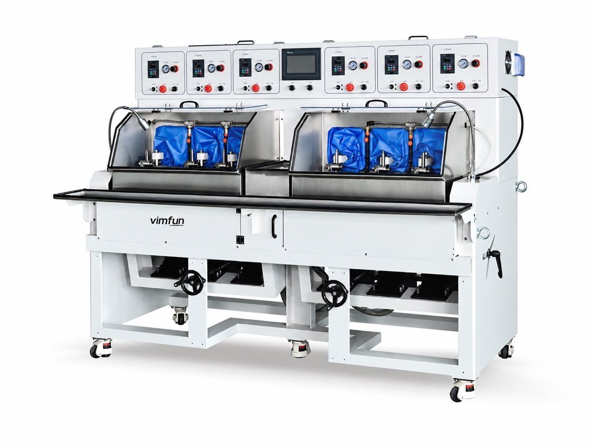
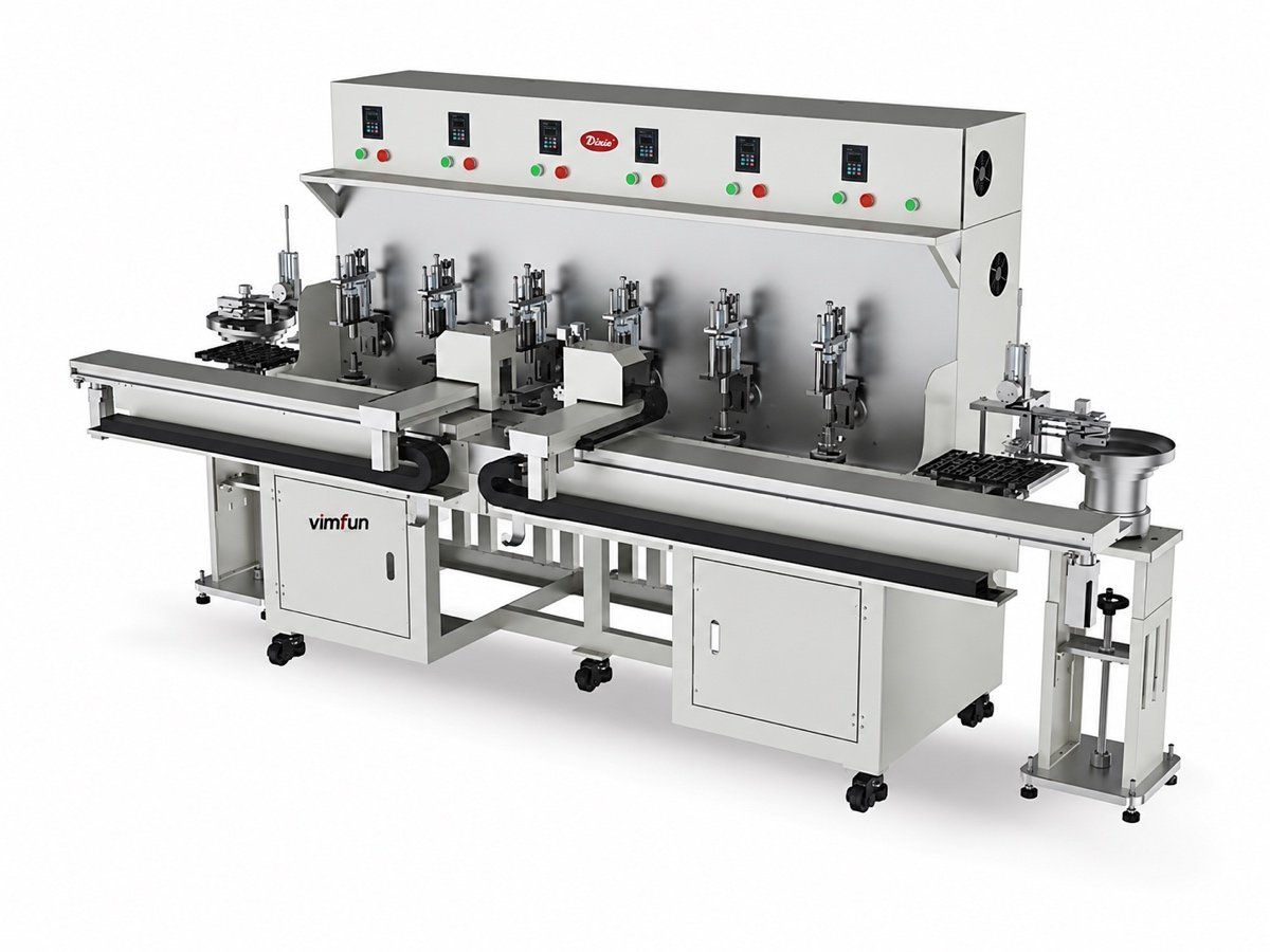
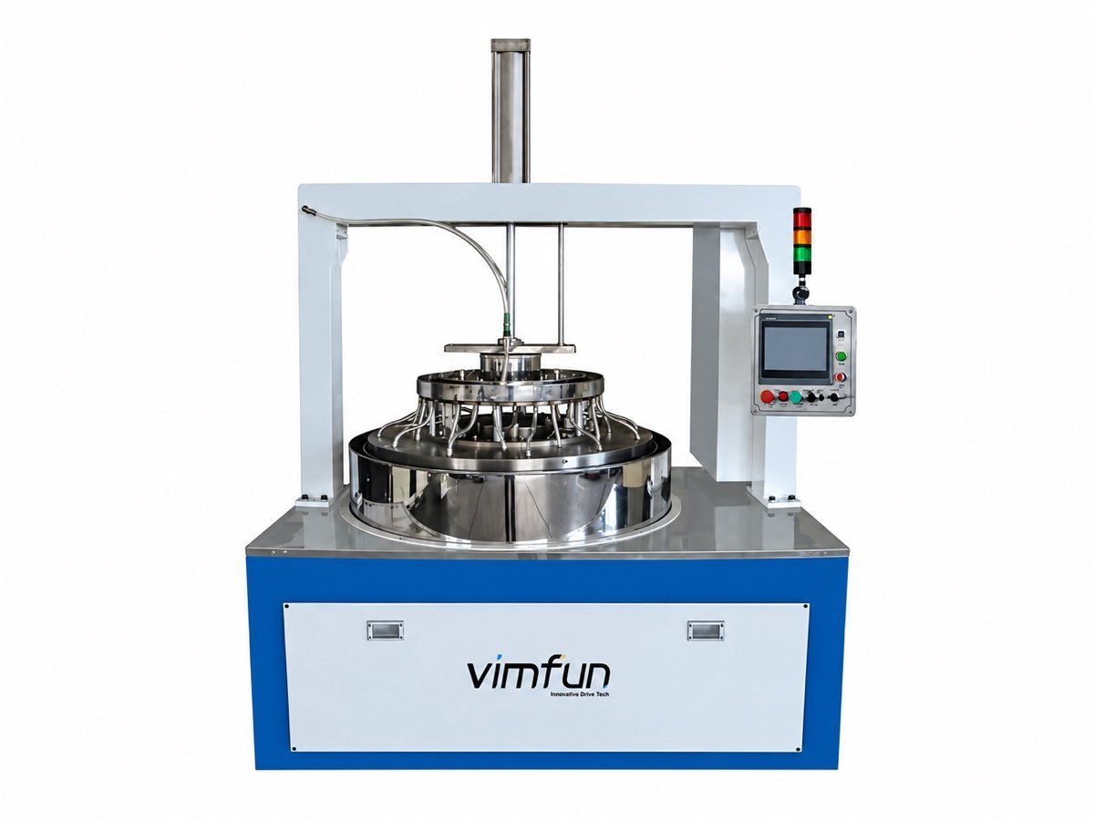
The full polishing range by geometry is on the optical lens polishing machine page; how these materials compare across the line is on optical lens materials. Sister material pages: optical glass, quartz and ceramics; what drives the quotation is on the price page.
Send three parts, not three pages of specification
Slurry, pressure and blocking are settled by running your crystals, free, on the matching machine. You get back the cycle time, the surface we reached and the fixture we would quote.
Arrange a process trial- Crystal type and, for single crystals, the cut
- Face count and the angles that matter
- Size, thickness and batch quantity
- Surface and form tolerance, in ISO 10110 terms if you have them
Free trial run on your own parts, freight at your cost · ISO 9001 · CE · 12-month warranty · 8-hour response