
Ceramic Grinding Machine
A ceramic grinding machine is judged by how it delivers slurry, not by how hard it can push. Ceramics do not flow before they break — every joule you put in comes back as heat and micro-fracture.
Why ceramics punish the coolant, not the wheel
Three properties change the job, and all three point at the same place — what happens in the last millimetre before the abrasive meets the part.
Hard, and brittle all the way
There is almost no plastic deformation ahead of the cut. Material leaves as micro-fracture, which means the abrasive dulls quickly and the surface you are left with is a field of small fractures rather than a smeared layer.
Heat stays where it is made
Most technical ceramics conduct heat poorly compared with metal. Energy concentrates at the contact zone instead of spreading into the part, so the delivery of slurry — where, and how much — decides whether you get a finish or a crack.
Parts are usually flats, not lenses
Substrates, windows, rings and polyhedra rather than radii. That changes the whole process chain: batch lapping and facet work carry more of the load than curve generating does.
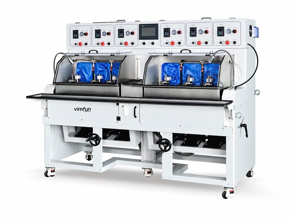
On the FP-6X tilt-axis machine the slurry can be fed by peristaltic drip rather than the recirculating pump used for glass. It is the single configuration choice that separates a ceramic grinding machine from a glass one in our range — ask for it by name when you enquire.
Which ceramics and part shapes does it cover?
Every ceramic grinding machine in this range is built for optical-grade finishing of small and medium parts — Ø10–80 mm on the polishing side, larger on the lapping plate.
| Part | Typical shape | Which station does the work |
|---|---|---|
| Substrates and flats | Both faces parallel, thickness held across the batch | Double-side lapping between plates |
| Windows and covers | Flat, edges and corners finished | Lapping, then edge polishing |
| Polyhedra and facets | Flat and angled faces, indexed | Faceting — rough, fine and polish in one setup |
| Spherical and flat faces | Radii and plano faces, Ø10–80 mm | Tilt-axis fine grinding and polishing |
- The ceramics we see most alumina, zirconia and aluminium nitride, alongside sapphire and the optical crystals, which behave the same way at the contact zone.
- Material data we cross-check against published engineering properties such as the Accuratus ceramics tables when a drawing gives only a trade name.
- Drawing language optical tolerances written to ISO 10110, so we can tell which station your tolerance really depends on.
- Before we quote grade, sintered condition and whether the part is already near net shape — a pressed blank and a ground blank are different jobs.
Where does a ceramic grinding machine sit in the line?
Not where a glass machine sits. A ceramic grinding machine usually follows a sintered or sawn blank straight into flat work, and only reaches a curve generator when the part genuinely has a radius.
Where a ceramic part does carry a radius, the generating side of the range is on the optical lens grinding machine page, and the way the stations connect into one line is set out on the complete fabrication line page.
What goes wrong on ceramics, and what stops it?
Every one of these traces back to energy at the contact zone. That is why a ceramic grinding machine is specified around slurry and pressure rather than around spindle power.
| Defect | Where it starts | What stops it |
|---|---|---|
| Edge chipping | Unsupported rim at entry and exit | Chamfer early, support the rim in the fixture, reduce pressure at the edges of the stroke |
| Micro-cracking below the surface | Too much pressure with too little abrasive present | Metered drip feed, lower pressure over more time — slower is cheaper than scrap |
| Abrasive dulling and glazing | No plastic flow to keep the grit cutting | Fresh slurry at the contact zone rather than recirculated, shorter dressing interval |
| Thickness and parallelism spread | Substrates finished one face at a time | Batch lapping on the DL-290/395, where the load sets the tolerance |
| Form drift across a batch | The polishing plate wearing thinner as it works | Plate zero-point calibration compensating for wear, as on the MF-3 |
None of this calls for a bigger machine. The upgrade we are asked for most often — more spindle power on a ceramic grinding machine — is the one that makes all five worse, because the extra energy has nowhere to go except into the part.

Which machine for which ceramic part?
Shape decides, and on ceramics the shape is rarely a lens. Flat substrates where both faces must stay parallel belong on the lapping plate. Parts with angled faces — prisms, polyhedra, indexed flats — belong on the faceting machine, which roughs, fine-grinds and polishes in one setup instead of moving the part between three. Panels whose edges and corners have to be optically clean go to the edge polisher.
Only when the drawing shows a radius does the question return to curve generating, and then the material changes the wheel and the feed, not the machine. If you are unsure which of the four your part belongs to, send one — that is a five-minute answer with the part in hand and a long argument without it.
Sapphire belongs to the same family for our purposes: same slurry discipline, same pressure discipline, same failure modes. A machine specified around your alumina or zirconia parts will normally take sapphire work as well, which is worth knowing before you buy twice.
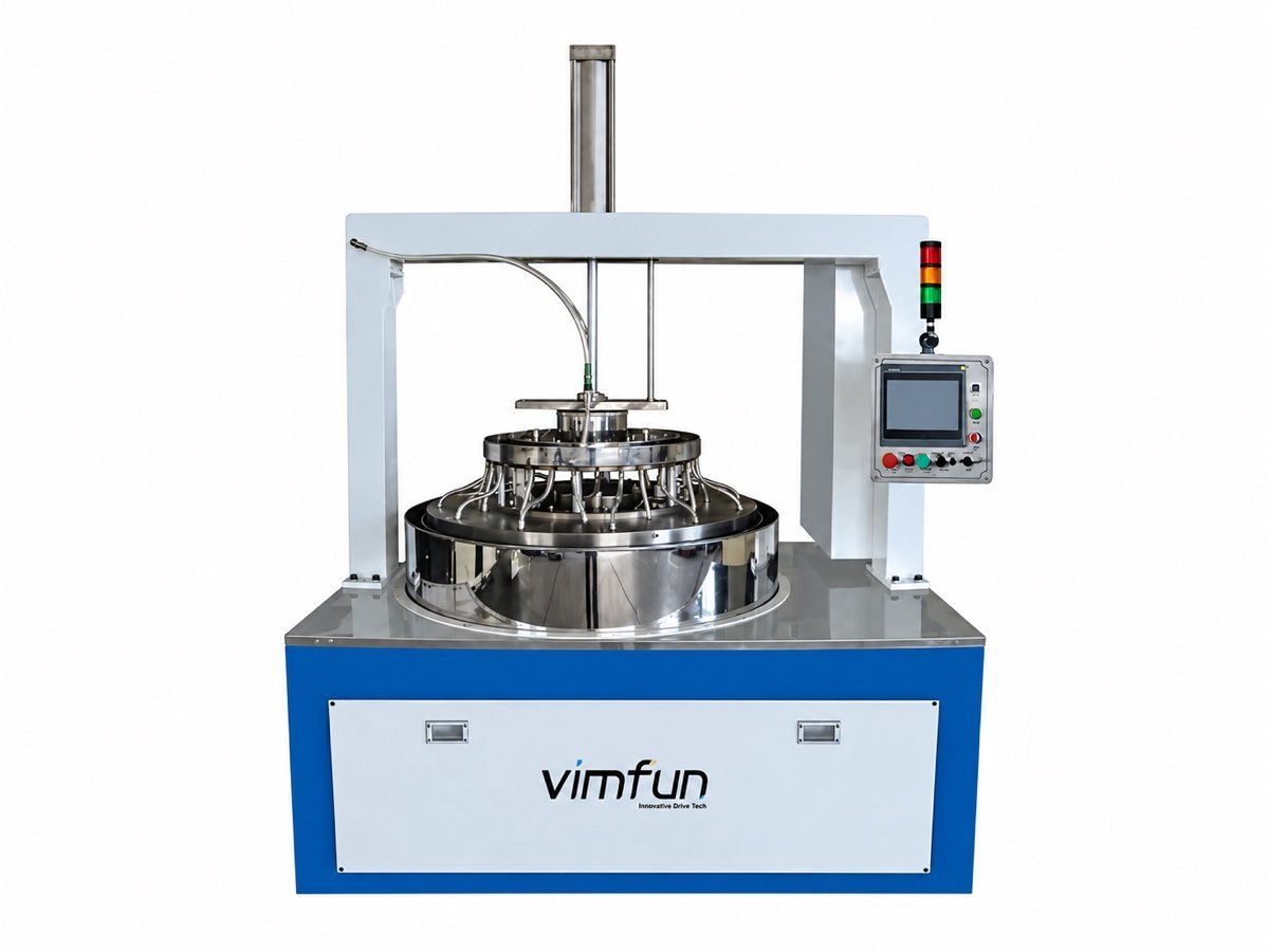
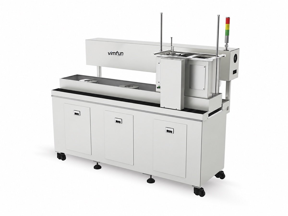
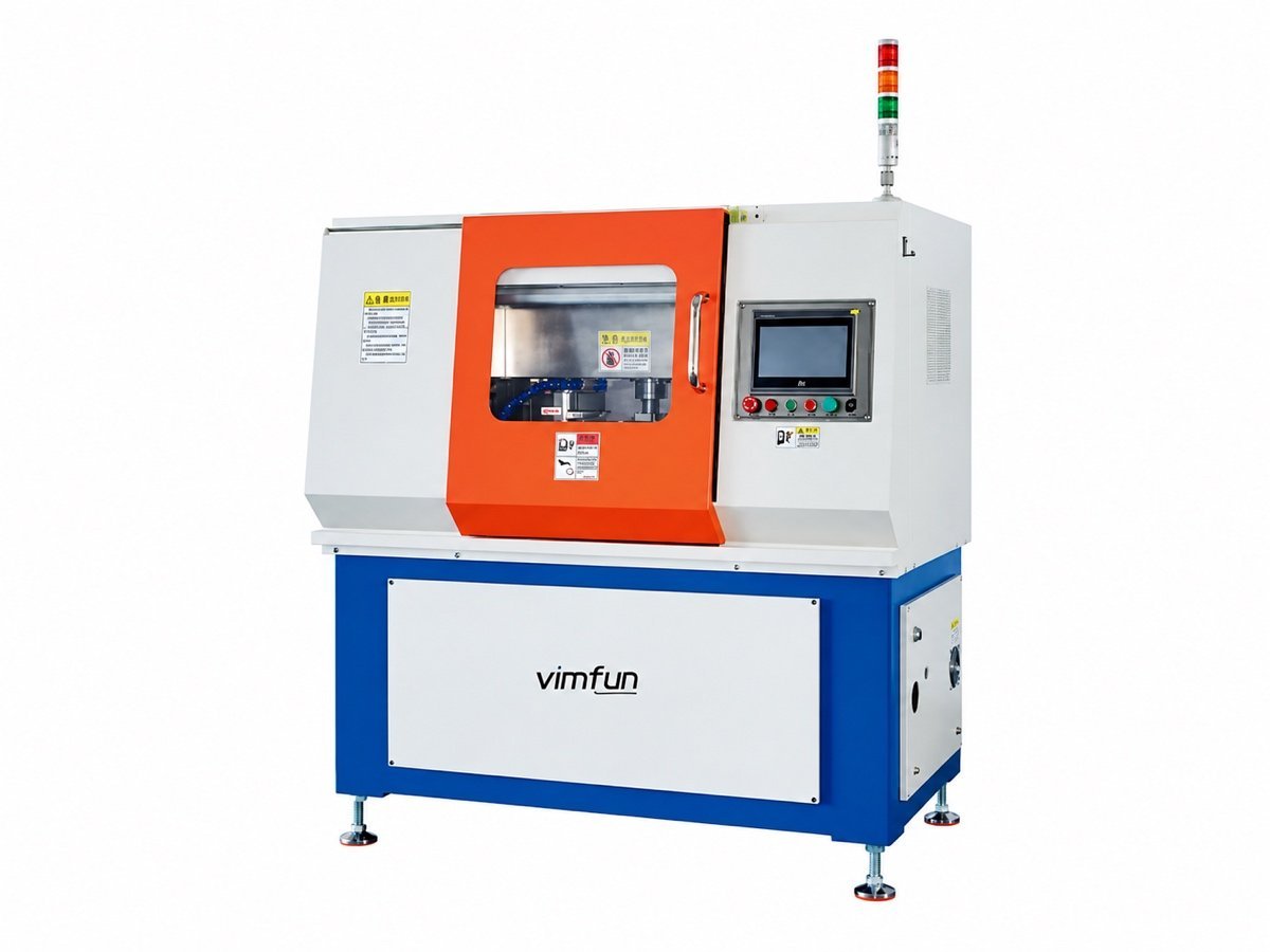
Fine grinding and polishing options are collected on the polishing range; the way ceramic behaves alongside the other hard materials we work is on optical lens materials. Sister material pages: optical glass, quartz and optical crystals; what drives the quotation is on the price page.
Ceramics are proven with parts, not paperwork
Grades and sintered conditions vary more than the datasheets suggest. Send your own parts and we run them free on the matching machine, then report the cycle time, the finish and the slurry setting we used.
Arrange a trial run- Ceramic grade and sintered condition
- Flat, faceted or radiused — and which face matters
- Size, thickness and batch quantity
- Whether blanks arrive pressed, sawn or near net shape
Free trial run on your own parts, freight at your cost · ISO 9001 · CE · 12-month warranty · 8-hour response