
CNC Optical Centering Machine EG-120L
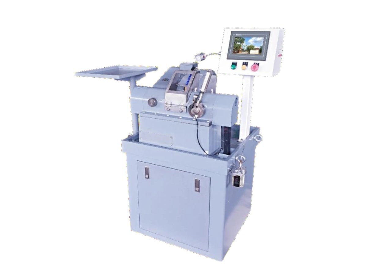
A horizontal CNC optical centering machine that clamps a lens between two bell chucks, lets it settle onto its own optical axis, then grinds the outside diameter true to that axis. Ø1.8–120 mm, twin servo axes, fully enclosed.
What this machine makes, and what happens before and after it
By the time a lens reaches this machine both faces are already finished. The radii are generated, the surfaces are polished, and the part is optically correct — except for one thing. Nobody has yet told the lens where its edge should be. The blank was sawn round, but round about what? Not about the optical axis, because the optical axis is defined by the two polished faces, and no upstream machine has referenced it.
That is the job of a CNC optical centering machine: find the line joining the two centres of curvature, then grind the outside diameter concentric with it. After this step the barrel of the mount and the optical axis of the lens are the same line, which is the whole point of the exercise.
Everything upstream is covered by the optical lens grinding machine range and the polishing range. Everything downstream is coating and assembly, which we do not build.
The generating and polishing machines decide what shape the lens is. A CNC optical centering machine decides where the lens is — relative to the tube it will eventually be screwed into.
How does a CNC optical centering machine find the optical axis?
It does not measure it. It lets the lens find the axis by itself, using nothing but two bell rims, a light clamp and the right spindle speed.
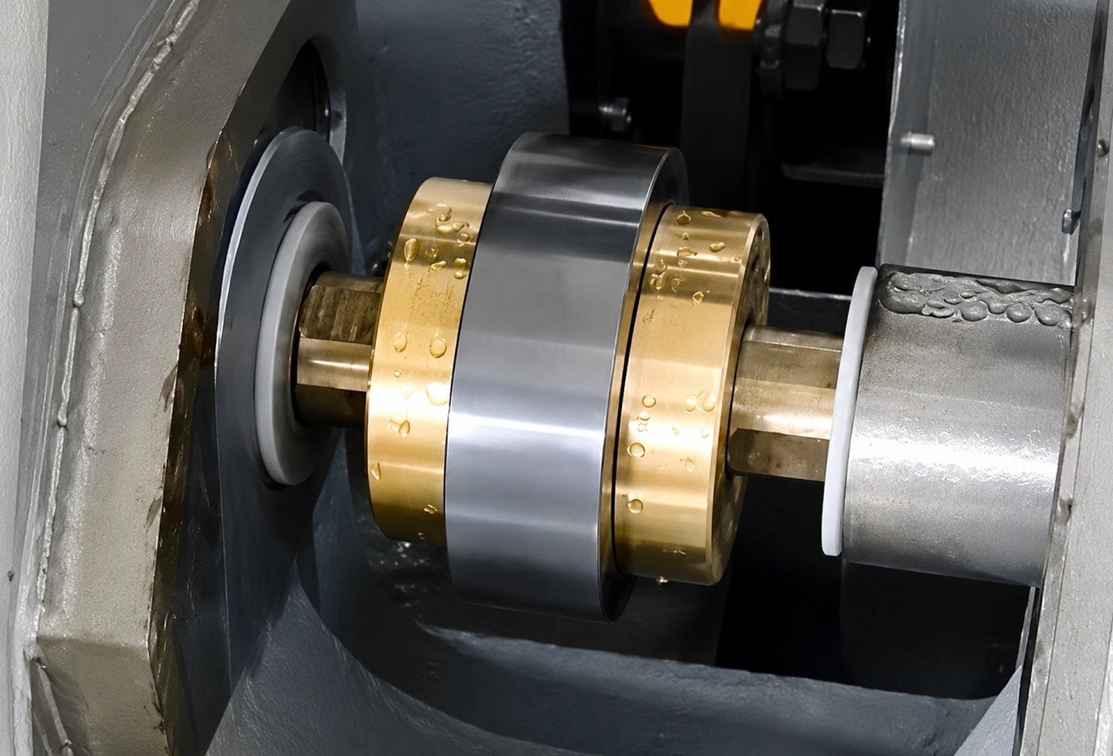
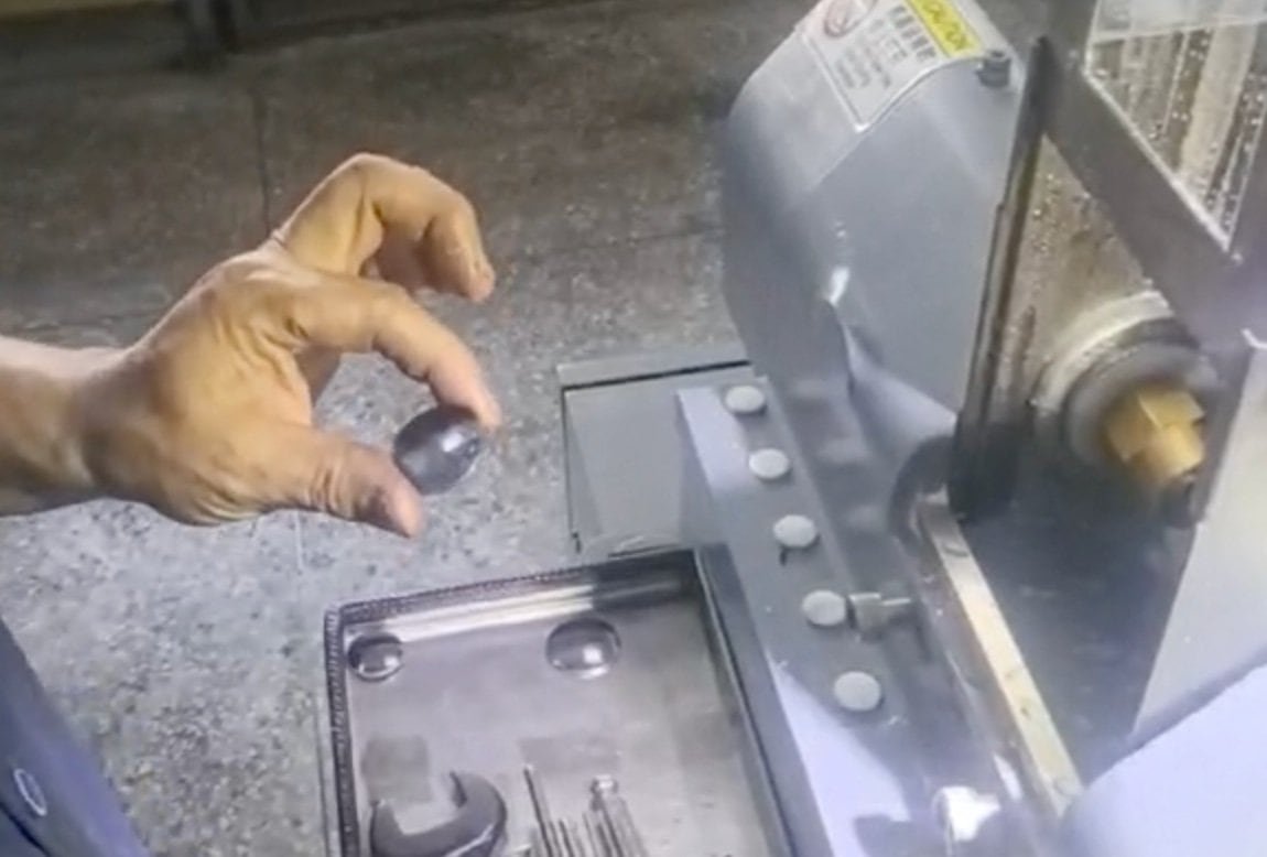
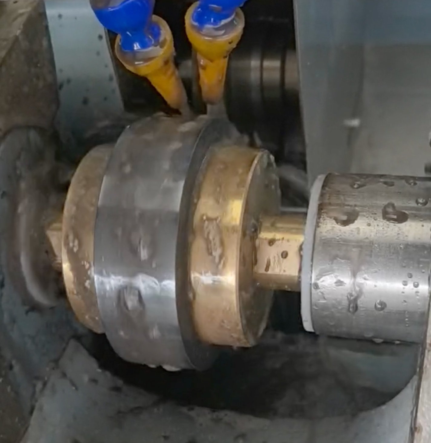
The lens is held on a single horizontal holder spindle made of two halves. Both carry an M20 × 1 thread — right-hand on the fixed end, left-hand on the moving end, so that the running direction tightens both chucks rather than backing one of them off. The chucks themselves are bells: short hollow cones whose rims touch the polished face in a circle rather than at a point.
Load a lens between two bell rims, clamp it lightly and spin it up, and the part will not stay where you put it. Each rim pushes on a spherical surface, and the only position in which those two pushes balance is the one where the line joining the two centres of curvature lies along the spindle axis. Anywhere else there is a sideways component, and the lens slides until that component disappears. That is why the holder spindle on a CNC optical centering machine is settable across its whole range instead of running at one speed: the alignment step wants speed, the cut wants control.
- Alignment, at the top of the range — light clamping force, high speed, the part free to migrate on the rims until the runout collapses
- Grinding, at the low end — the clamp goes hard, the lens is now locked on its own optical axis, and the wheel comes in
- Holder spindle 0–300 rpm, freely settable — different glasses, weights and bell sizes settle at different speeds, and the right pair is found on trial parts
- Holder spindle torque, 8 N·m — enough to hold a clamped part against the full depth of cut without the chuck creeping
The diamond wheel runs at 3,500 rpm on its own spindle, mounted at the rear of the machine, and feeds in under servo control. Because the part is turning slowly at that moment and the wheel is turning fast, the edge is generated rather than scraped — which is what keeps chipping down on the exit side.
The bell chucks are not accessories, they are tooling. Bell diameter has to suit the lens diameter and its radii, so tell us the range of elements you run and we will specify the set with the quotation.
Four things the servo axes decide for the operator
Both linear axes on this CNC optical centering machine are servo driven on linear guideways, each repeating to 0.003 mm. That is what turns a set of hand-wheel judgements into numbers typed on a screen.
Constant depth of cut, set as a number
Rather than winding the wheel to a stop and taking whatever is left, a CNC optical centering machine of this class removes the edge at a depth of cut you set digitally and it then holds. Diameter comes out consistent from the first part to the last, and the ground surface stays fine and even.
Multi-stage control over edging and chamfering
The whole sequence — rough, finish, then the chamfer on each side — runs as separately controlled stages instead of one pass. Heat into the glass drops, and with it the two defects that matter here: surface burn and edge chipping.
Wheel life measured in months, not weeks
A servo feed never loads the wheel harder than the program says, so the diamond layer wears evenly. This is most noticeable on sapphire and other superhard materials, where an overloaded wheel glazes over in a shift.
The guard drives itself up and down
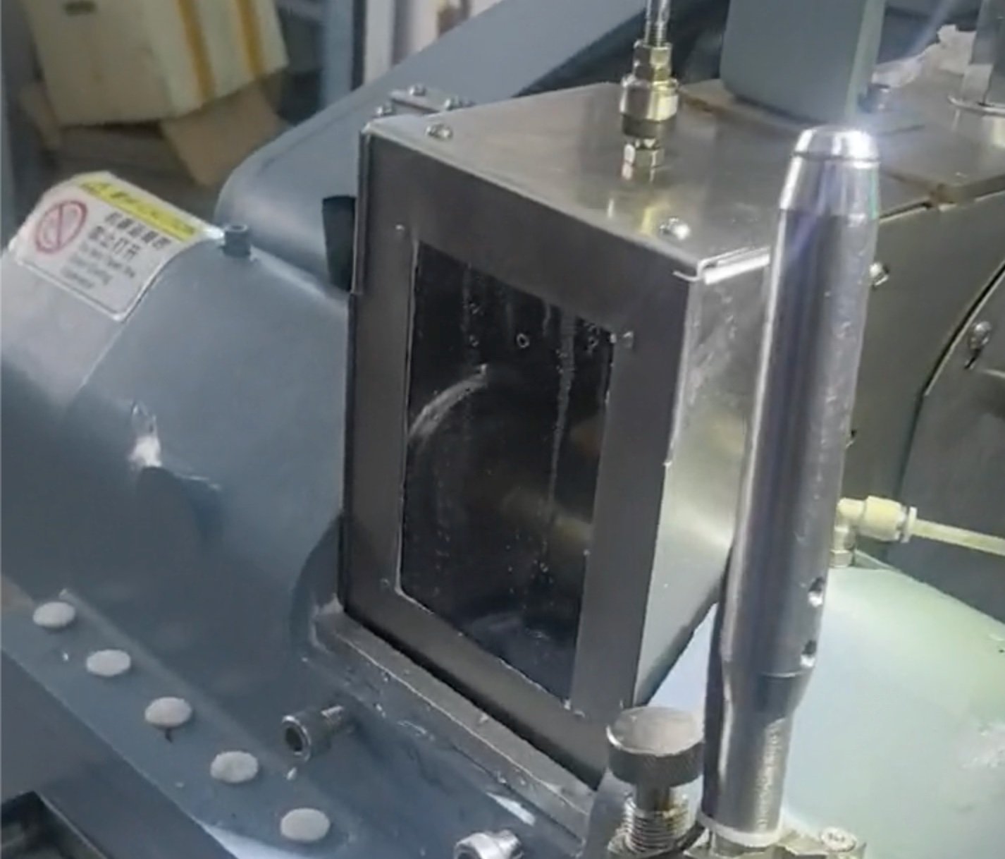
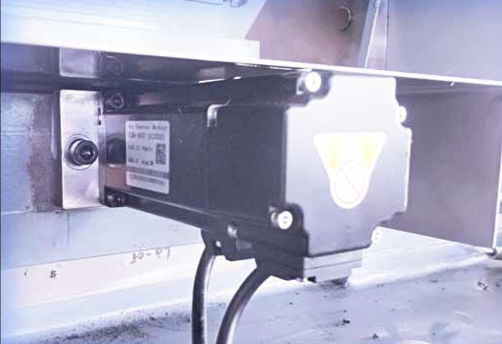
The enclosure is positively driven, not spring-balanced, so it cannot drift open under vibration or drop when a hand is inside. The motor sits at the rear behind the enclosure, which also keeps coolant mist off it.
What happens in the ten seconds after the guard closes
Ten seconds is the shortest cycle quoted for this CNC optical centering machine; the actual figure is whatever you set for the part in front of you, because every stage below is a settable parameter rather than a fixed dwell. Thin parts and small diameters run near the bottom of that range, thick sapphire near the top.
| Element | Motion | What it controls |
|---|---|---|
| Holder spindle | Rotation, 0–300 rpm | Self-alignment, then the part speed during the cut |
| Holder spindle slide | Servo traverse, 400 W | Where along the edge the wheel works — diameter and both chamfers |
| Wheel spindle | Rotation, 3,500 rpm | Cutting speed at the diamond rim |
| Wheel spindle slide | Servo infeed, 400 W | Depth of cut per stage, held constant |
| Clamp | Two force levels | Free to migrate, then locked |
| Coolant | Circulating, 90 W pump | Flushes the cut and keeps the glass cool |
Centring accuracy on a machine of this type is a setting capability, not a per-part measurement. The operator establishes it with a centroscope on the first parts of a batch and the machine then repeats it; there is no closed-loop gauge reading every element. If your acceptance procedure needs a recorded figure for every piece, say so before you order — it changes what you should be buying.
Which materials and part sizes can it handle?
| Item | Capability |
|---|---|
| Operations | Outside-diameter edging concentric to the optical axis, plus chamfering, in one clamping |
| Lens diameter | Ø1.8 – Ø120 mm |
| Part thickness | Under 40 mm recommended |
| Parts per cycle | 1 — single spindle, single element |
| Materials | Optical glass, sapphire and other superhard substrates; wide, large-format elements are specifically within scope |
| Cycle time | From 10 s, then to the operator’s setting |
| Wheel | Diamond, Ø160 × 30H7 × 30T, 8–30 mm working thickness |
| Wheel speed control | Fixed at 3,500 rpm as standard; variable-frequency drive available as an option |
| Chuck truing | Optional fixture corrector for dressing the bell chucks in place |
Because the part is located by its own polished faces rather than by a fixture, the material matters less here than it does upstream — what decides the result on a CNC optical centering machine is the radii, the clear aperture and the diameter tolerance on your drawing. If the drawing is dimensioned to the ISO 10110 framework, send it with the enquiry and we will tell you which bell set the job needs.
Technical specifications
Every figure below is standard on this CNC optical centering machine. For elements above Ø120 mm, the same principle is built at a larger scale as the EG-185L.
| Number of spindles | 1 axis |
| Lens diameter range | Ø1.8 – Ø120 mm (thickness under 40 mm recommended) |
| Working time per part | From 10 s, then user setting |
| Holder spindle thread | M20 × 1 — RH fixed end, LH moving end |
| Holder spindle speed | 0 – 300 rpm, freely settable |
| Holder spindle rotary motor | 8 N·m |
| Holder spindle traverse motor | 400 W servo |
| Holder spindle traverse repeatability | 0.003 mm |
| Wheel spindle speed | 3,500 rpm |
| Wheel spindle motor | 750 W |
| Wheel infeed motor | 400 W servo |
| Wheel infeed repeatability | 0.003 mm |
| Diamond wheel | Ø160 × 30H7 × 30T (8 – 30 mm thick) |
| Wheel drive belt | 6-rib poly-V, PJ686 |
| Coolant pump | 90 W |
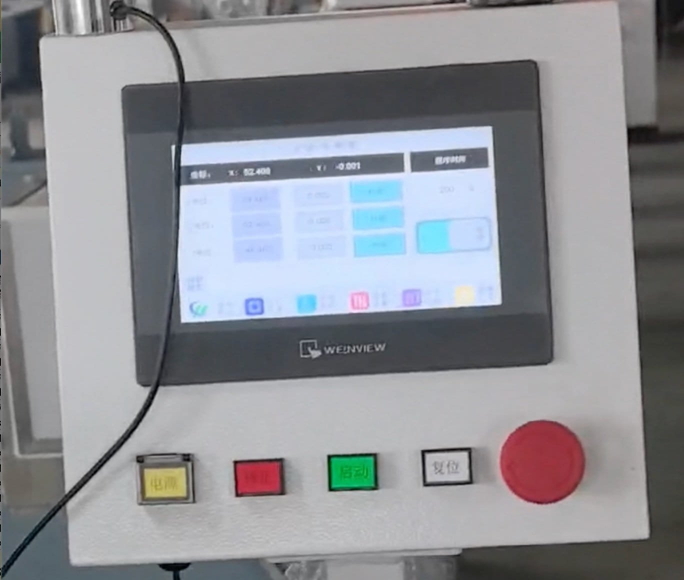
| Control | PLC with 7″ touchscreen |
| Overall dimensions (L × W × H) | 1000 × 1000 × 1500 mm |
| Total weight | approx. 500 kg |
Options
| Option | What it does |
|---|---|
| Wheel spindle VFD | Makes the wheel speed variable instead of fixed — useful when one machine has to cover both soft crown glass and sapphire |
| Fixture corrector | Trues the bell chucks in situ, so a worn rim is dressed rather than replaced |
Principal components
Brands are indicated for reference. Equivalent components of the same or higher grade may be fitted; the stated performance is maintained in all cases.
| Component | Brand / standard |
|---|---|
| PLC and HMI | Premium PLC brand, 7″ colour touchscreen |
| Servo motors and drives | Premium servo brand |
| Wheel spindle bearings | Angular-contact, P4 class, matched pair |
| Linear guideways | Premium linear-motion brand |
| Contactors and electrical | Premium industrial control brand |
| Wheel drive | 6-rib poly-V belt |
Main assemblies and what each one is for
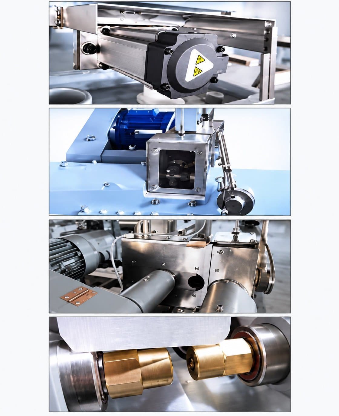
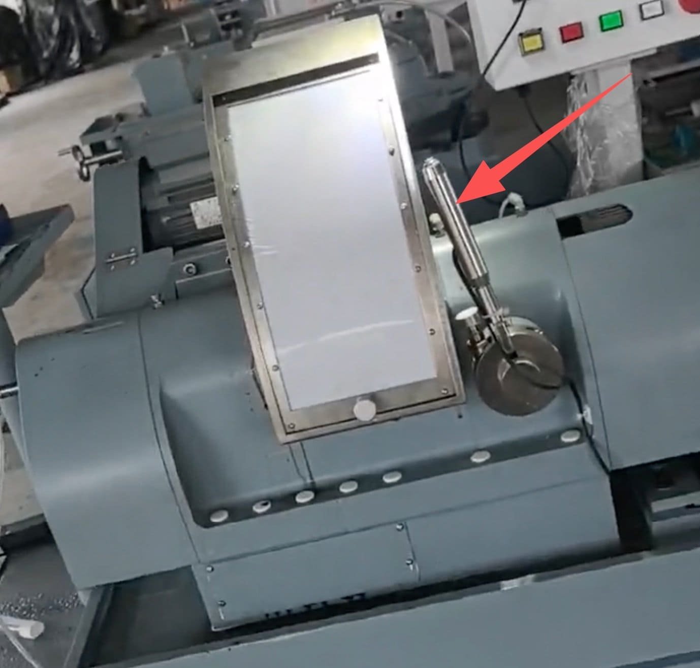
Seven groups make up this CNC optical centering machine. If something needs attention on the shop floor, this is the vocabulary your operator and our service engineer will share.
| Assembly | Function |
|---|---|
| Holder spindle group | Two-part spindle with bell chucks, RH and LH threaded, running the alignment and grinding speed bands |
| Holder traverse slide | 400 W servo on linear guideways positioning the part along the wheel for diameter and chamfers |
| Wheel head | Diamond wheel, 3,500 rpm spindle on a matched P4 bearing pair, motor mounted at the rear |
| Wheel infeed slide | 400 W servo carrying the depth of cut, repeatable to 0.003 mm |
| Enclosed guard | Full enclosure with a positively driven lift, containing coolant mist and glass swarf |
| Coolant system | 90 W circulating supply with the tank in the machine base |
| Control group | PLC, 7″ touchscreen and an integrated operating handle, with the cabinet in the base |
When should you choose a different machine?
Four machines in our range clamp a lens between bells and grind its rim, and all four settle the part onto its own optical axis before they cut. What separates a CNC optical centering machine from a profile edger is not how it finds the axis — it is the size range it takes, what defines the finished outline, and who puts the part in the chuck. Buying on the wrong one of those three is an expensive way to find out.
- Parts above Ø120 mm — go to the EG-185L large optical centering machine, which covers Ø50–185 mm and adds a taper micro-adjustment for long edges
- Non-round outlines — squares, D-shapes, cover glass, anything copied from a former belongs on the EG-80 profile edge grinding machine or its automatic version, the Auto-EG-80. They centre the part exactly as this machine does, then let a copy former decide the shape; this machine finishes it round
- Loading you never touch — the Auto-EG-80 puts each lens into the chuck with a pick-and-place head. Here an operator loads every part, which is the right trade below Ø120 mm and on short runs
- Polished edges on flat 2D and 2.5D panels — that is peripheral polishing, done on the EP-220C, not here
- Unpolished blanks — there is no optical axis to find yet. Finish both faces first
Not for architectural or decorative glass, and not for ophthalmic Rx laboratories — this is production equipment for precision optical elements, not for spectacle lens edging.
If you are still working out which stage of the line you are actually short of, the edging and centring overview compares all of these machines side by side.
Utilities, environment and safety
Electrical supply, compressed air, coolant, floor loading and the ambient conditions the machine is to run in are confirmed with us for each order, together with the safety and protective arrangement supplied with it. These figures depend on the voltage and frequency of your site, the material you are running and the destination market, so we do not publish a single set of them here.
Send us the site conditions with your enquiry and we will return the utility and environmental requirements in writing, before the order is placed.
On a CNC optical centering machine the diamond wheel and the bell chucks are both process items, chosen for the material, the diameter range and the radii you run. They are quoted separately from the machine.
What happens after the machine is installed?
The same terms apply to every machine we ship, wherever in the world it goes.
| Warranty period | 12 months from final acceptance |
| Response during warranty | Response within 8 hours · solution proposed within 24 hours · issue resolved within 48 hours, including procurement, installation and commissioning of parts |
| Outside the warranty | Service and spare parts available for the life of the machine; damage from misuse or abnormal operation is chargeable |
| Certification | CE |
Specifications are subject to change as a result of continuous design improvement. Minor differences may occur at certain parts. For a binding specification, refer to the order confirmation.
See the machine running
The self-alignment step at the top of the speed band, and a full cycle on an optical glass singlet. Watch the part settle before the clamp goes hard — that half-second is what a CNC optical centering machine is really selling.
02 — Germanium lens centering and edge grinding (demonstration)
Send one drawing and a few blanks
A CNC optical centering machine is easy to specify badly from a datasheet, because the number that decides the job is not on the datasheet — it is the bell set. Send us one element drawing with the diameter, both radii, the centre thickness and the centration tolerance you have to hold, together with a few polished parts of your own.
We run them, return them and send the process sheet with the quotation. The trial run itself is free; you cover the freight for the blanks. Quotations are FOB by default, with CNF and DDP available on request.
12-month warranty · free trial run on your own blanks
Optics customers include Edmund Optics and Coherent
Related equipment and reading:
- Large optical centering machine EG-185L — the same principle for Ø50–185 mm elements
- Edging and centring machine range — all four machines compared
- Automatic lens profiling edger Auto-EG-80 — for shaped outlines
- Optical lens fabrication line — how the six stations connect
- Full equipment range