APPLICATION NOTE / OPTICAL POLISHING

Lens Blocking and Deblocking: Pitch, Wax and Fixtures

A lens can pass a surface check while attached to its block and fail after release. That does not automatically mean the polisher lost accuracy. The part may have been held in a strained shape, bonded unevenly or measured before its temperature stabilized.

Lens blocking establishes support and a reference for machining. The choice of adhesive, support geometry and release method affects how the surface is generated and whether that result survives deblocking. Select the holding method together with the polishing motion and the final inspection condition.

01 — What lens blocking must control

A good block holds the optic securely without forcing it into a shape that disappears after release. It also locates the workpiece relative to the machine and keeps the intended surface accessible to the tool.

Start from the part drawing. Identify the locating surface, center thickness, edge thickness, curvature and any finished surface that must be protected. A fixture suitable for a thick blank may not support a thin finished lens in the same way.

Record the blocking operation as part of the process route, rather than treating it as preparation outside the quality system. Bond material, batch, heating history, support area and seating method can all affect repeatability. Without that record, a later form error is difficult to distinguish from tool wear or machine setup.

Some processes use carriers or mechanical retention instead of adhesive. Therefore, lens blocking is not an unavoidable requirement for every polishing operation. It is one workholding approach with specific benefits and limitations.

02 — Compare pitch, wax and mechanical retention

Do not select an adhesive solely because it releases easily. It must provide adequate support throughout the process and remain compatible with the optic, coolant and cleaning route.

Holding approachUseful characteristicsMain qualification questions
Pitch-based blockingCan conform to a prepared support and accommodate established shop methodsDoes the selected grade resist creep at the actual process temperature?
Blocking waxOffers product-specific bonding and release behaviorAre the heat cycle, bond thickness and residue removal acceptable?
Mechanical fixture or chuckAvoids an adhesive heat cycle and may simplify repeat loadingDoes contact force distort, mark or displace the part?
Carrier or pocket supportCan hold multiple parts in compatible flat-processing routesAre thickness, protrusion, retention and contact conditions controlled?

There is no single blocking temperature for “wax” or “pitch.” Use the consumable supplier’s current instructions and qualify the actual material combination. A nominal softening point is not a complete process window.

Mechanical retention also has a cost. Reducing clamp force may allow movement; increasing it may change the form. The correct setting is established by machining and measuring released parts, not by making the fixture feel secure by hand.
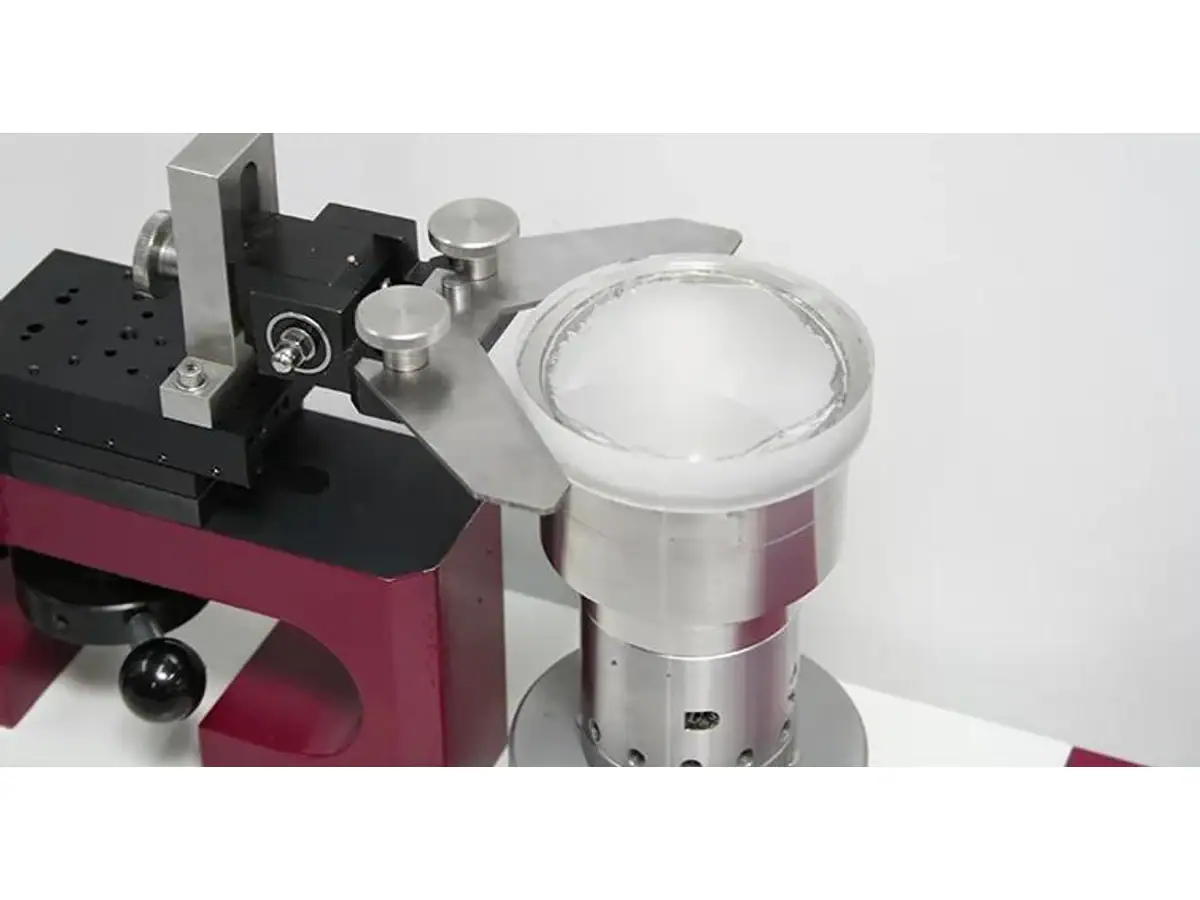
Lens held in an optical processing fixture
Example of lens workholding. The bonding material and blocking method are not identified in this photograph.

03 — Match support geometry to the polishing motion

Lens blocking sets the relationship between the optic and the polishing tool. On a curved part, errors in seating, block curvature or axis location can change contact and removal distribution. A small position error should not be confused with a change in the desired optical radius.

Think of the workpiece surface, its center of curvature and the swing reference as separate geometry that must be brought into the intended relationship. A conceptual sketch can show those relationships, but a production setup requires the machine’s own alignment procedure and dimensions.

Check seating without relying on adhesive to fill an uncontrolled gap. An uneven bond layer can shift the part as it cools or creeps. Support contamination can introduce a local high spot. Repeating the same machine settings will not correct either problem.

Inspect the block and locating features before blaming the polishing lap. For a multi-station machine, identify the fixture assigned to each spindle; otherwise, a persistent fixture error may appear to be random variation between parts.
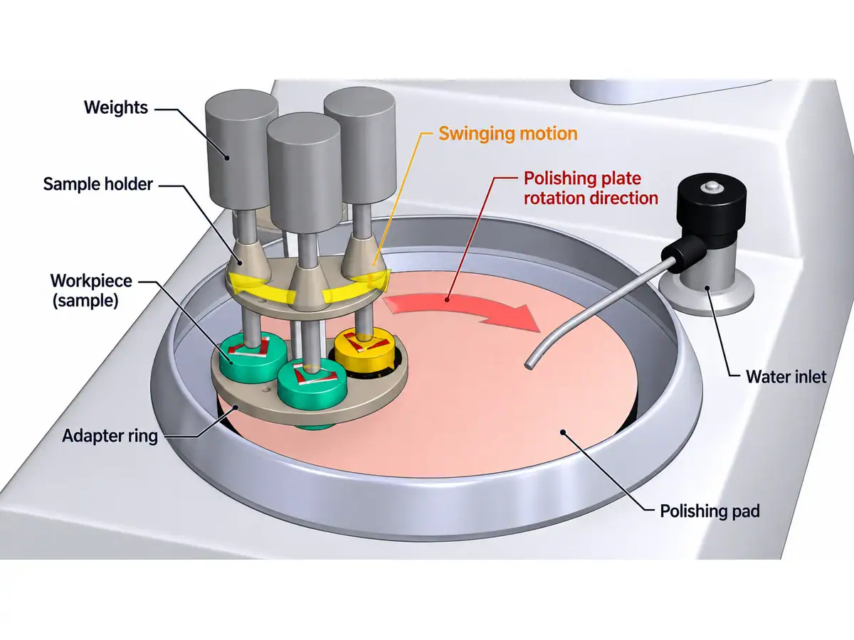
Conceptual sample-holder oscillation and polishing-plate rotation
Illustrative flat-sample polishing arrangement showing holder oscillation and plate rotation. This is not a spherical-lens blocking or centre-of-curvature diagram.

04 — Use the machine family’s selection rule carefully

Within Vimfun’s published range, the FP-4U upper-swing configuration is positioned for concave lenses, while the FP-4L lower-swing configuration is positioned for convex lenses. This distinction helps narrow the machine choice before developing the fixture.

It is a product-family selection rule, not a universal claim that all upper-swing or lower-swing machines worldwide have the same capability. Confirm curvature, size, contact geometry and tooling for the specific workpiece.

The fine-grinding and polishing comparison also describes independently controlled stations in the six-spindle upper-swing configuration. Independent operation can support mixed work, but does not remove the need to qualify each fixture and recipe. Operator access, guarding and changeover procedures still govern how parts are exchanged.

Review lens blocking at the machine-selection stage. A nominal diameter range is not proof that the finished lens can be held, accessed and released without damage.

05 — Batch loading needs a location map

Multi-part blocking can improve handling efficiency, but it makes individual position traceability valuable. Number the positions and keep that numbering through final inspection. If the same block location repeatedly produces a different result, investigate seating, support and contact before adjusting every part’s recipe.

Control the bond layer and loading sequence according to the qualified procedure. Parts with different initial thicknesses or curvatures may not share the same effective contact condition. Mixing them simply to fill a block can sacrifice consistency for apparent utilization.

Track both block yield and final accepted-part yield. A block that survives machining with every part attached is not automatically a successful batch. Losses during release, cleaning and final measurement belong in the production record. The optical lens yield discussion provides the wider context for counting those losses.

For lens blocking trials, retain a map of part position, incoming dimensions, recipe and final result. That map is more useful than a single average taken across the batch.

06 — Deblocking is a controlled process step

Plan how the bond will be released before selecting it. Thermal, solvent-assisted and mechanical release methods have different compatibility requirements. A method approved for one glass and coating stack may damage another.

Avoid sudden heating or cooling outside the material and consumable supplier’s procedure. Do not use prying force as the routine solution to an adhesive that has not released. Release support should prevent the optic from falling, colliding with neighboring parts or landing on its finished face.

Separate the cleaning process from the assumption that the bond is gone. Thin residue can affect later inspection or coating even when the component looks clean under general lighting. Define how residues are checked and which surfaces may be contacted during handling.

After lens blocking and release, allow the part to reach the specified inspection condition. Record whether measurements were made on the block, immediately after release or after stabilization. Those are different states and should not be mixed in a capability report.

07 — Investigate distortion using a paired check

When the released part changes form, compare a documented sequence rather than repeating polishing immediately.

Result patternFirst checksUseful comparison
Passes while blocked, fails after releaseHolding stress, bond distribution, inspection temperatureMatched blocked and released measurements
Error follows one fixtureSupport cleanliness, seating geometry, wearSame part family on a qualified alternative fixture
Error follows a block positionLocal bond layer, contact distributionPosition map across several batches
Surface remains contaminatedAdhesive compatibility and cleaning sequenceAgreed residue inspection before coating

Re-polishing a strained part without correcting the support may reproduce the same failure. A controlled lens blocking trial should isolate the holding variable while keeping the tool and measurement method consistent.
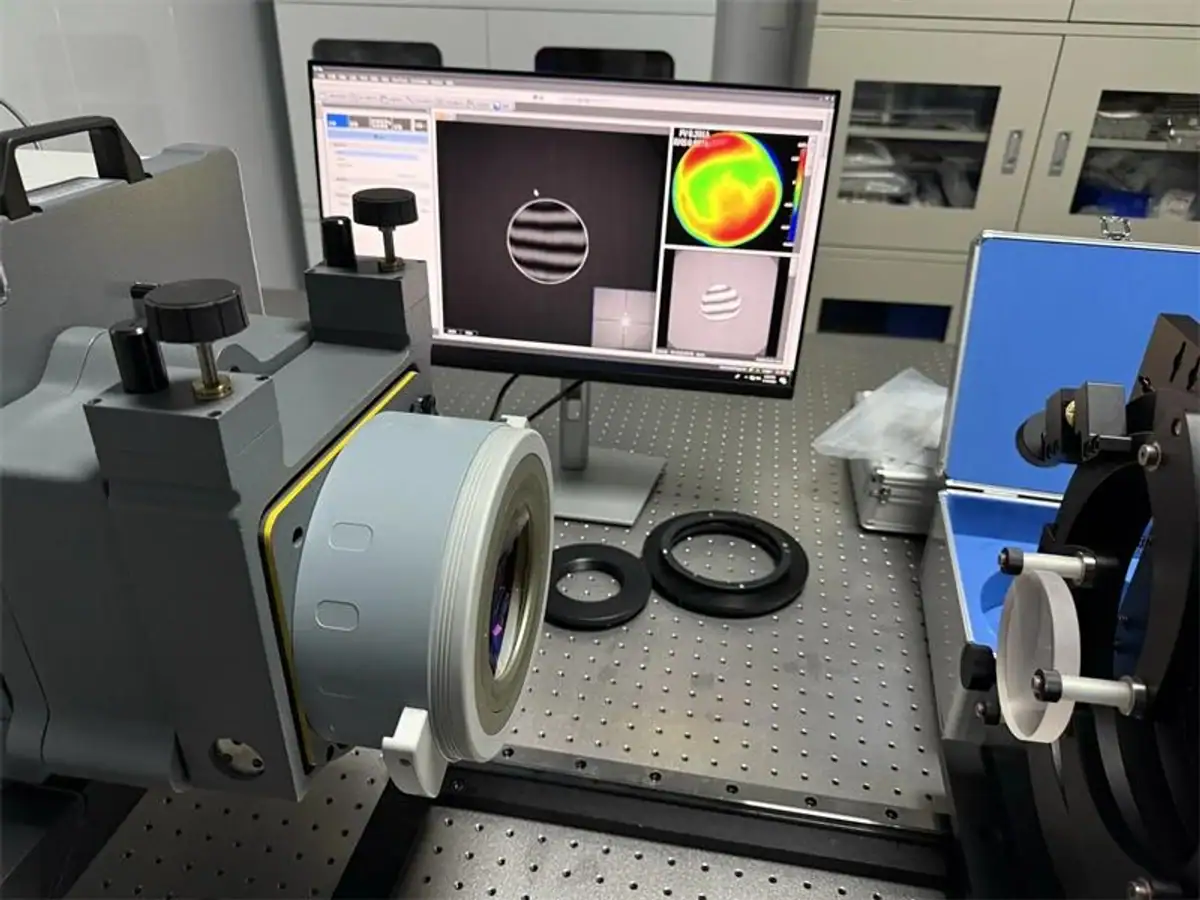
Optical component on a metrology setup
Optical inspection setup example. This photograph does not establish a before-and-after deblocking comparison.

08 — When adhesive-free holding is the better choice

A carrier-based or mechanical route can be attractive when geometry, thickness and retention are compatible with it. It may reduce heating and cleaning work, but it is not a universal replacement for conformal support on a thin or strongly curved optic.

Compare total accepted output, including loading, release, cleaning and inspection. A shorter bonding cycle can lose its advantage if it creates more rework or requires manual recovery after machining.

Send the drawing, material, finished-surface condition and intended batch size for an application review. Include the current lens blocking and deblocking method, especially when the reported defect appears only after release. That information helps separate a workholding problem from a machine-selection problem.

Scroll to Top