Infrared Dome Grinding in Germanium, ZnS and Sapphire
A curved protective window can meet its center thickness while having an unacceptable thin region near the rim. Its inner and outer surfaces may also pass separate form checks while being incorrectly related to one another. Infrared dome grinding needs a geometry and measurement plan that treats the shell as one component.
For civilian thermal-imaging housings and industrial temperature-monitoring windows, begin with the optical band, environment and finished drawing. Confirm whether the specified material, curvature and wall profile suit the intended system before choosing tooling. A machine’s ability to generate a concave or convex surface does not establish its ability to process every deep shell.
01 — Define the shell, not just two radii
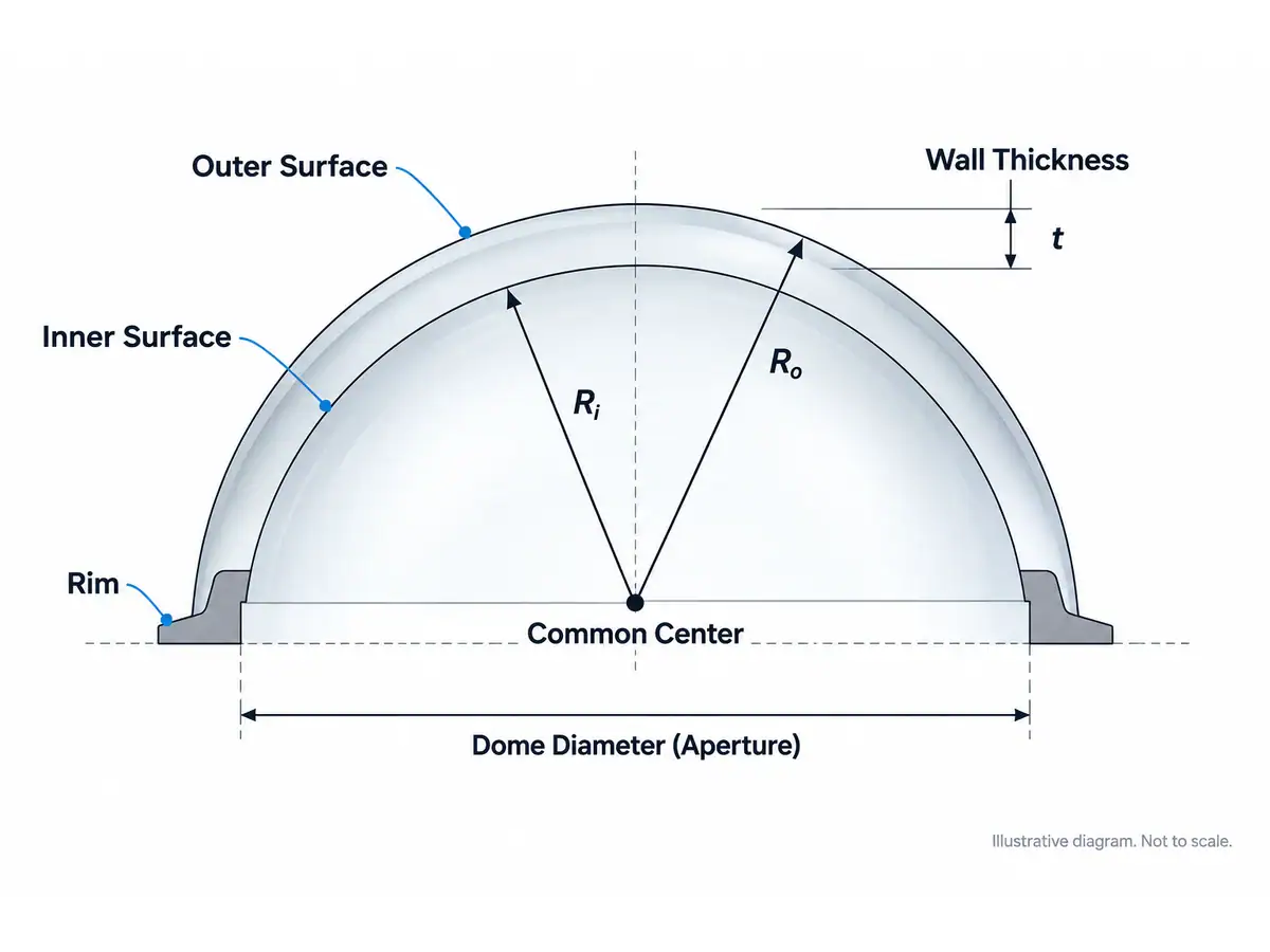
Specify inner and outer geometry, aperture, rim features and the relationship between the surfaces. State how wall thickness and alignment will be measured. A nominal radius pair is incomplete when local thickness, concentricity or an edge transition controls acceptance.
For ideal concentric spherical surfaces, the radial wall thickness is the difference between the outer and inner radii. That statement depends on the shared center. A center-thickness reading along one line cannot prove that the real part satisfies the concentric condition everywhere.
Infrared dome grinding should therefore begin with a datum scheme and a thickness-map requirement appropriate to the design. Mark the functional region separately from any sacrificial rim or holding allowance. This prevents a fixture feature from being confused with the finished optical aperture.
02 — Check material against the operating band
Germanium, ZnS and sapphire are not interchangeable windows for every infrared system. Their transmission, coating options and environmental behavior differ. Confirm the actual grade and spectral requirement with the optical designer and material supplier.
Avoid selecting a material solely from a mechanical property or a broad description such as “infrared transparent.” The system requirement includes wavelength, temperature and the finished optical path. A commercially available material is not automatically appropriate for the intended detector band.
| Material choice | Information needed for process review | What must remain application-specific |
|---|---|---|
| Germanium | Grade, blank geometry and required surface quality | Operating band, coating and thermal conditions |
| ZnS | Exact material grade and supplied form | Optical performance and qualified finishing route |
| Sapphire | Grade, crystal orientation where specified and geometry | Spectral requirement and direction-sensitive processing |
The infrared optics equipment overview provides a route through the available operations. It should support, rather than replace, the optical material decision.
03 — Tool access in infrared dome grinding
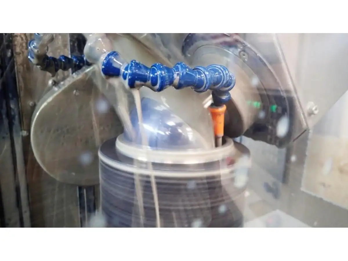
As a surface becomes deeper, tool clearance and contact conditions become more restrictive. Check the tool envelope, spindle access, fixture clearance and liquid-delivery path throughout the planned motion. A center point that is reachable does not prove access to the rim.
Use a geometry review before committing material to the machine. Include tool diameter, holder geometry and the stock present at intermediate stages. Interference can occur during roughing even if a tool clears the finished surface in a simplified drawing.
For infrared dome grinding, separate the machine’s quoted radius range from the usable depth and opening of the actual part. Workholding and access may be the limiting factors even when the nominal radius appears acceptable.
Do not assume that online sagitta measurement covers every wall-thickness or concentricity requirement. It measures a defined feature in a particular setup. Its relationship to the final part must be demonstrated.
04 — Design support for the changing wall section
A blank becomes less stiff as material is removed. Support that is acceptable early in the route may distort or damage the later thin shell. Plan how the holding method changes, if necessary, as the geometry develops.
Review contact area, bond layer or clamp force and the surfaces used for location. A localized support point can affect the measured or machined shape. Adhesive release and cleaning also belong in the process plan when bonding is used.
In infrared dome grinding, a good in-fixture measurement is not sufficient evidence of released shape. Inspect under the specified final support condition after the part has stabilized. Record the difference between on-machine and released measurements rather than combining them into one result.
Consider a trial fixture or representative sacrificial workpiece when access and stiffness are uncertain. This can resolve the holding concept before valuable optical material is used for a complete finishing trial.
05 — Control the error introduced by the second setup
Processing the inner and outer surfaces often involves a change of reference or fixture. Every transfer can introduce an alignment error. The plan should identify which features carry the datum from one operation to the next.
Measure and preserve a meaningful reference before removing the original holding stock. If the reference disappears too early, the next station may have to locate from a less suitable surface or rely on an unverified assumption about concentricity.
For infrared dome grinding, record both setup alignment and the finished relationship between the surfaces. A fixture can repeat its own position while still locating the part incorrectly. Repeatability and correctness are different requirements.
Review which operation sets the rim and when it becomes a final feature. Rim finishing can change a locating surface or reveal edge damage that affects the next holding stage.
06 — Build an inspection plan that reaches the difficult regions
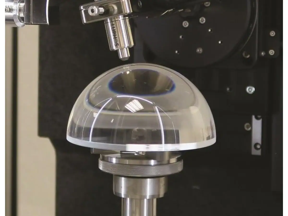
Choose methods according to geometry, access and the required uncertainty. A contact instrument may have limited reach; an optical method may require a suitable viewing or test configuration. Establish the usable measurement region before quoting a complete inspection result.
| Inspection item | Required definition | Common incomplete substitute |
|---|---|---|
| Surface form | Reference shape, aperture and evaluation method | A radius value alone |
| Wall thickness | Positions, datum and measurement method | One center reading |
| Surface relationship | Alignment or concentricity definition | Two independently passing surfaces |
| Rim condition | Finished boundary and defect criteria | General visual approval |
| Released geometry | Support and stabilization condition | Measurement while held in the machining fixture |
Infrared dome grinding trials should preserve raw profiles or maps with part identification. Missing data near a steep rim must be reported as a coverage limitation. It should not be replaced by extrapolated acceptance without an agreed method.
07 — Match the machine to the demonstrated geometry
Vimfun’s optical grinding equipment guide describes spherical and plane-generating options, including the G-100 and G-250 family. Those descriptions are a starting point for a geometry review, not proof of deep-dome capability on an unspecified shell.
The germanium grinding equipment discussion can help organize material-specific questions. Confirm the proposed blank, fixture, tooling, intermediate geometry and inspection method for the actual order.
For infrared dome grinding, ask the supplier to identify what has been demonstrated and what still requires a trial. Keep blank preparation, generating, fine grinding, polishing and inspection as separate scope items. An integrated enquiry is useful only when each stage has a defined output.
The thermal-imaging manufacturing route gives the wider civilian system context without replacing the component-level qualification.
Ask for a stage-by-stage stock sketch showing the planned holding allowance and the regions that remain accessible for inspection. Review it with both the machining and metrology teams. This is particularly useful when the final rim is also a locating feature, because removing it too early can compromise the reference needed for the second surface.
08 — Qualify the complete part before batch release
A useful trial follows the component through both surface operations, release, rim finishing and the agreed final inspection. Record where stock remains and where rework would become impossible. A thin region cannot be repaired by polishing its opposite surface further.
Include more than a single favorable sample when establishing production repeatability. Compare the effects of material variation, tool condition and setup transfer within the agreed trial scope. Define which changes require review before another batch begins.
Send the inner and outer drawings, wall-thickness requirement, material grade, operating band and annual quantity for an application review. The first decision in infrared dome grinding is whether the geometry can be supported, accessed and measured through the entire route. Nominal machine size is only one part of that answer.