A wafer can meet its nominal thickness and still be too thin to finish. One face may be bowed; a low area may carry a deep saw mark; an edge chip may extend into the required diameter. The grinder must remove those defects while preserving the finished geometry.
The right cutting allowance is the stock needed to reach the specified geometry, remove cutting damage and complete the qualified finishing sequence, with a margin for measured process variation. There is no reliable universal millimetre value for germanium, ZnSe, sapphire, quartz and optical glass. Start from the finished drawing, then qualify the blank using representative cuts and downstream trials.
This cutting allowance guide separates blank thickness from raw-material consumption and shows what to measure before releasing a batch.

01 — Build the cutting allowance budget from the finished part
For a plane-parallel part finished on both faces, use this starting relationship:
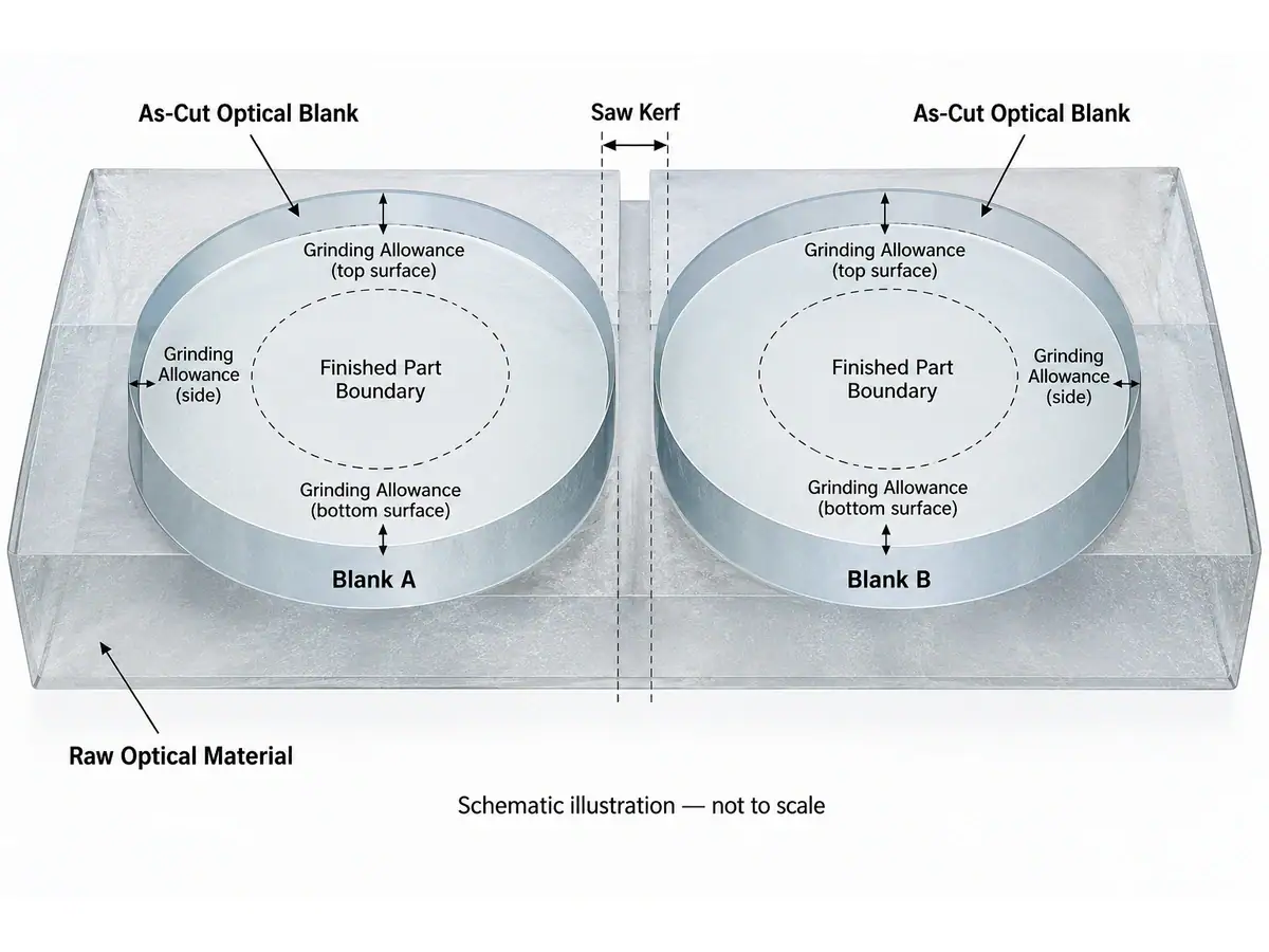
As-cut blank thickness = finished thickness + total planned removal from face A + total planned removal from face B.
Each face budget covers rough grinding, fine grinding and polishing, plus a justified process margin. The roughing allocation must already accommodate the measured shape error and cutting damage. Do not add a separate damage-layer allowance again if the qualified roughing removal already covers it.
For a curved lens, center thickness alone is insufficient. Position the finished lens envelope inside the blank and check the required stock across both surfaces, including the edge. The generating operation removes the material outside that envelope. A flat-wafer thickness equation cannot replace this geometry check.
| Budget item | What to establish | Where it belongs |
|---|---|---|
| Finished geometry | Thickness, curvature, diameter and clear aperture | Drawing and datum scheme |
| Roughing removal | Stock needed to generate shape and remove cutting defects | Per-face removal plan |
| Fine grinding | Removal needed after the preceding abrasive stage | Qualified finishing sequence |
| Polishing | Removal needed after fine grinding | Qualified finishing sequence |
| Process margin | Variation demonstrated across representative parts | Explicit reserve, reviewed after trials |
| Kerf | Material removed by each saw cut | Raw-stock consumption calculation |
Keep the units and conventions visible. “Allowance per face,” “total thickness allowance” and “radial edge stock” are different quantities. Mixing them can double a purchase specification before the first blank reaches the machine.
02 — Kerf consumes the ingot, not the remaining blank
A common budgeting error puts kerf inside the thickness of a wafer that has already been cut. Kerf is material lost between adjacent blanks. For a repeated slicing operation, the approximate material pitch is blank thickness plus measured kerf; end trimming and unusable remnants need separate treatment.
Vimfun’s published SG-40 germanium slicing page describes closed-loop cutting with kerf around 0.4–0.5 mm in its examples. That is a starting reference for the cutting configuration, not an allowance recommendation or a guaranteed result for every material. The page also lists edge-chipping performance, but an edge-chip measurement cannot establish subsurface crack depth across the face.
Measure the actual slot or stock consumption on representative cuts. Wire diameter alone does not capture abrasive protrusion, lateral motion and the resulting cut width. The separate kerf-loss guide explains why this distinction matters for material yield.
Compare alternative cutting methods at the same output requirement. Blade thickness, wire diameter and a laser’s nominal spot size are not interchangeable measures of usable blank yield. Include the subsequent cleanup and rejected blanks in the comparison.
03 — Bow and wedge can use up the local stock
The minimum usable stock matters more than an average thickness reading. A bowed slice may require considerable removal before both faces clean up. A wedged blank can reach the minimum permitted thickness on one side while saw marks remain on the other.
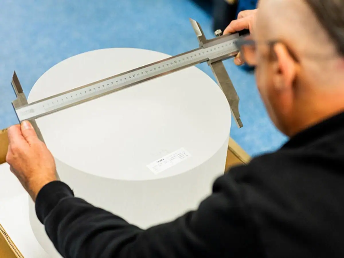
Map thickness at defined positions and measure face form relative to the intended processing datum. Thickness variation alone does not fully describe bow: two curved faces can remain approximately parallel. Record how the part was supported, because clamping or bonding can distort a thin blank during measurement.
Use these measurements to set the cutting allowance before production. If the stock distribution cannot contain the finished shape with the required cleanup reserve, increasing the polishing time will not rescue it. Review the cutting setup, support and cut direction before simply specifying a thicker blank.
Keep edge cleanup separate. A chip outside the finished diameter may be removed during edging, but one extending into the clear aperture can make the blank unusable. Neither case is solved automatically by increasing axial thickness.
04 — A smooth-looking face does not prove shallow damage
Saw marks describe surface topography. Subsurface damage describes cracks beneath that surface. A photograph, a roughness number or an edge-chip value is not a substitute for a qualified damage assessment.
Research by Hed and Edwards on optical-glass grinding found a relationship between surface roughness and damage depth under the investigated grinding conditions. That does not supply a universal conversion factor for a different wire-cut material and process. Use a validated relationship only within its demonstrated conditions.
The manufacturing consequence is straightforward: a smoother appearance after grinding does not, by itself, confirm that the previous damage layer has been removed. Agree how representative samples will be assessed and how the result will inform the removal schedule. Our subsurface-damage guide provides the connection to subsequent grinding and polishing.
Set the cutting allowance using this process evidence. Avoid adding an arbitrary “SSD percentage” to every material, particularly when the roughing allocation already includes damage removal.
05 — Material changes the qualification priorities
Use material identity to decide what needs closer examination, not to assign an unsupported fixed allowance. A universal ranking from “least” to “most” stock would conceal differences in geometry, abrasive condition, orientation and workholding.
| Material | Relative qualification priority | What to confirm before reducing stock |
|---|---|---|
| Germanium | High attention to material yield and brittle edge loss | Face form, edge condition and downstream cleanup; confirm through customer-material trial cuts |
| ZnSe | High attention to support, handling and damage | Condition after cutting and release from the fixture; confirm through customer-material trial cuts |
| Sapphire | High attention to removal effort and crystal orientation | Actual cutting and grinding response for the specified orientation; confirm through customer-material trial cuts |
| Quartz | Separate fused silica from crystalline quartz | Grade, orientation where applicable, face form and damage; confirm through customer-material trial cuts |
| Optical glass | Grade-specific assessment | Glass type, surface condition and finishing route; confirm through customer-material trial cuts |
This table ranks concerns rather than promising a material-by-material thickness recipe. For expensive blanks, reducing kerf and reducing finishing stock solve different parts of the yield problem. The germanium kerf-loss discussion belongs in the raw-material calculation, while the removal budget belongs in process qualification.
06 — Carry the measurements into the grinding handoff
A useful cutting allowance specification is a handoff document. Include the drawing revision, material grade, blank dimensions, datum convention, face measurements and acceptance method. Identify which defects rough grinding must remove and what stock must remain for later stages.
Vimfun’s optical lens grinding equipment guide connects the cutting output to the next machine selection. An equipment setting or in-process gauge reading is not automatically the final part acceptance result. Confirm the measurement method and check the blank after release from its processing fixture where relevant.
For a germanium blank-to-lens workflow, carry the same blank identification through cutting, generating and finishing. Otherwise, a successful polished part cannot be traced back to the cutting conditions that produced it.
07 — More cutting allowance is not free insurance
Extra stock has to be removed somewhere. For a flat circular face of unchanged diameter, additional removal volume is face area multiplied by the added thickness. Doubling diameter therefore multiplies that extra volume by four. Grinding time need not rise in exactly the same proportion: loading, approach moves, tool condition and allowable removal rate also matter.
For germanium and ZnSe, compare usable finished parts per purchased blank or ingot, rather than cutting speed alone. The cost calculation should include material lost in the kerf, stock ground away, abrasive consumption, handling and rejects discovered after finishing.
Reduce cutting allowance in controlled steps. A thinner blank is an improvement only if the finishing route still meets the drawing reliably. Review these trade-offs across the optical fabrication line, with cutting and grinding assessed together.
08 — Qualify the budget before committing the batch
Start with representative material and the actual finished drawing. Record wire configuration, feed, support method and the relevant machine settings. Inspect blanks after release, then carry selected samples through the intended grinding and polishing sequence.
Keep one record of the evidence:
- As-cut thickness map and face-form measurements.
- Edge condition relative to the finished diameter and clear aperture.
- Removal at each stage, with the measurement method identified.
- Final geometry, surface acceptance and rejected-part reasons.
- The settings and material lot associated with each sample.
Approve the cutting allowance after reviewing variation across the trial, not just the best-looking wafer. Repeat qualification when a material grade, geometry, fixture or significant process condition changes.
Send the material, blank size, finished drawing and required output. Request free sample cutting to establish the as-cut condition and discuss the downstream stock budget. Grinding and polishing validation, where required, should be agreed separately.