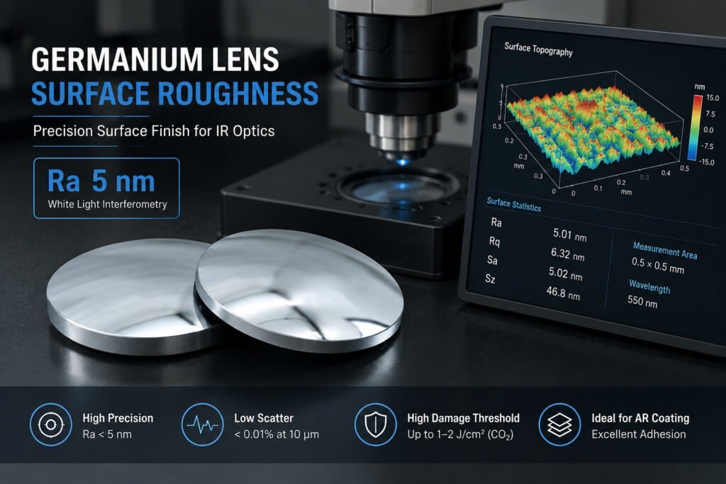
Ra 5 nm is not an exotic number for germanium. It is a class of finish that established polishing chemistry reaches routinely — and that a badly controlled process will miss no matter how long you polish. The reason germanium lens surface roughness gets specified this tightly is scatter: in the 8–14 μm thermal band, surface texture that would be invisible in a visible-light optic becomes a measurable loss mechanism.
This guide covers what the Ra 5 nm class means in physical terms, how germanium lens surface roughness is driven by every stage from the wire saw cut onward, how it should be measured and written into a drawing, and the three failure modes that stop shops reaching it.
Why Germanium Lens Surface Roughness Matters in the LWIR Band
Visible-light optics tolerate more surface texture than people expect, because at 0.4–0.7 μm most polishing marks are already sub-wavelength. At 8–14 μm, where germanium is the workhorse lens material, the relationship between wavelength and texture changes — and not in the direction intuition suggests. Longer wavelength does not make roughness irrelevant; it changes which spatial frequencies scatter and how the loss is distributed.
Total integrated scatter from a smooth surface follows the Rayleigh-Rice relation, TIS ≈ (4πσ/λ)², where σ is the RMS roughness. That distinction is where most specifications go wrong: σ is Rq, not Ra. For a surface with Gaussian height distribution Ra is roughly 0.8 × Rq, so a spec written in Ra has to be converted before it goes into the scatter budget. Plug the numbers in at λ = 10 μm and the shape of the problem is clear — σ = 5 nm gives a TIS under 0.01% per surface, while σ = 50 nm gives roughly 0.4%. Small in absolute terms, decisive in a system where signal-to-noise margin is the constraint.
Two other effects ride along with the same parameter:
Laser damage threshold. In CO₂ laser systems using germanium passive optics, surface peaks concentrate field intensity, and each peak is a potential initiation site. The mechanism is well established even where the numbers are application-specific: rougher surfaces fail at lower fluence than well-polished ones of the same material and coating. If damage threshold is part of your specification, it has to be qualified on your own parts and your own coating — a roughness figure alone does not predict it.
AR coating conformity. Germanium optics for thermal imaging are almost always AR coated for the 8–12 μm band, typically a multi-layer stack with ZnS/Ge or DLC outermost. The coating conforms to the substrate, so substrate texture translates into coating thickness variation and optical path length variation across the clear aperture. Coating a rough substrate does not smooth it — it copies it.
What Does Ra 5 nm Actually Mean?
Ra is the arithmetic mean of absolute profile deviations from the mean line, over a defined sampling length. At Ra 5 nm the average deviation is five nanometres — around 1/2000th the diameter of a human hair, and about 1/80th the wavelength of blue light.
The number on its own is close to meaningless, though, and that is the part worth internalising. Ra is an average, so it hides exactly the defects that kill an IR optic: a single deep scratch, a patch of orange peel, a pitted zone over exposed subsurface damage. Two germanium surfaces can return the same Ra and behave completely differently in a thermal imager. This is why a full topographic map matters more than a single-number readout, and why the sampling conditions have to travel with the specification.
Reaching the Ra 5 nm class is therefore not a polishing problem. It is a whole-route problem — the polishing step can only remove so much material before it starts creating its own defects, and what it has to remove was decided upstream at the saw and the grinder.
From Saw Cut to Polished Surface
Germanium lens manufacturing follows a fixed sequence — blank cutting, grinding, polishing — and each stage sets the input condition for the next. The final finish is only reachable when every earlier stage has delivered what the next one needs.
Stage 1: Wire Saw Cutting
The as-cut surface is the roughest the part will ever be, and it sets the ceiling on the germanium lens surface roughness everything downstream has to work toward. Its texture is set by wire grit size, wire linear speed, feed rate and coolant delivery. On our endless-loop machines the wire runs at up to 52–61 m/s depending on model, with working tension matched to wire diameter — 80 N on a Ø0.35 mm loop, 170 N on Ø0.8–1.0 mm — and held automatically during the cut. Aggressive feed and worn wire both push the as-cut texture rougher, which pushes the grinding burden up and extends total process time.
The cut also leaves a layer of subsurface damage — disrupted crystal beneath an apparently clean surface. That layer has to be fully removed during grinding. If it is not, polishing thins the surface until the damage front is exposed, and it shows up as anomalous scatter and reduced transmission in a finished lens. How deep it runs depends on the ingot, the wire condition and the feed, so it is established by destructive test on the actual material rather than read off a table.
Stage 2: Grinding
Grinding is where germanium lens surface roughness is actually won or lost. It does two jobs at once: it removes the damage layer from cutting, and it generates the optical geometry — radius of curvature on a lens, flatness on a window. For germanium the usual route is a sequence of bonded diamond pellet tools stepping down in grit:
| Stage | Typical diamond grit | What this stage is for |
|---|---|---|
| Coarse grind | 40–60 μm | Bulk removal — clears the saw-cut texture and the damage under it |
| Medium grind | 15–25 μm | Establishes geometry; removes coarse-grind damage |
| Fine grind | 6–9 μm | Brings the surface into range for lapping |
| Pre-polish lap | 1–3 μm | Leaves the polisher a surface it can finish without excessive removal |
That last line in the table is the governing rule of the whole sequence, and it is where most yield problems originate. The fine-grind-to-lap transition is the natural verification point: localised high spots or a non-uniform pattern after fine grinding mean damage from cutting is still present and more material has to come off before polishing starts.
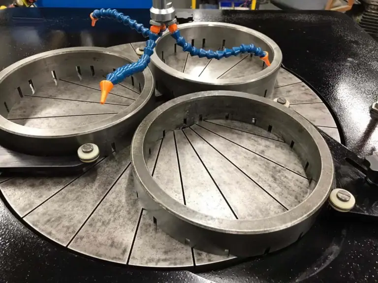
Our infrared optics grinding machine runs germanium with removal rates set for germanium’s particular combination of hardness and brittleness, rather than applying glass parameters to a more fragile material. The germanium lens grinding equipment overview covers the machine options for this stage.
Stage 3: Polishing
Germanium polishes efficiently compared with sapphire or silicon carbide, so polishing is rarely the bottleneck in reaching a given germanium lens surface roughness. The difficulty is not removing material — it is removing it uniformly across the full aperture without introducing new defects.
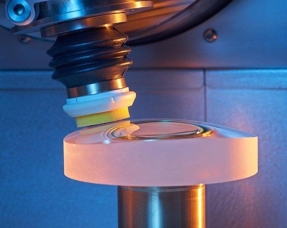
Polishing chemistry is conventional: colloidal silica slurry or fine cerium oxide on a polyurethane or pitch lap. Final measurement should be taken at several locations across the aperture — centre, mid-radius and near-edge — because germanium’s dn/dT lets local temperature vary the removal rate, which can leave a centre-to-edge gradient on larger apertures that a single centre reading will never show. Our germanium optics polishing machine page covers the equipment side.
Three Failure Modes That Stop You Reaching Ra 5 nm
Each of these three produces a surface that fails on germanium lens surface roughness for a different reason, and each has a different fix.
Orange peel. Shallow, closely spaced bumps that develop when the polishing removal rate outruns the surface relaxation rate. Visible under oblique illumination and detectable interferometrically. It appears when polishing pressure is too high for the compound in use, or when the lap runs hot during extended polishing. Once it develops, polishing will not smooth it — the part goes back to fine grinding.
Pitch contamination. Pitch laps embed abrasive carried over from earlier grinding stages when the between-stage cleaning protocol is loose. Embedded particles produce random deep scratches, and a single one disqualifies the surface regardless of what the Ra readout says.
Residual subsurface damage. If polishing starts with damage still present, it removes the surface layer and eventually exposes the damage front — micro-pitting and anomalous topography under interferometric inspection. The fix is always to go back to grinding, which is expensive at that point. This is the single most common reason a shop that “polishes properly” still cannot hold the finish.
How Should Ra 5 nm Be Measured and Specified?
At the Ra 5 nm level, germanium lens surface roughness can be measured properly by two techniques. A third one in common use is not appropriate at all.
White light interferometry. Non-contact, fast, and it returns a full topographic map rather than a single number — which is what reveals the orange peel, pits and scratches an Ra value averages away. The usual choice for production monitoring.
Atomic force microscopy. Sub-nanometre vertical resolution over a small field. Too slow for production, but definitive for reference measurements and for resolving ambiguous interferometry results on critical parts.
Contact profilometry is not appropriate here. A stylus tip is orders of magnitude larger than the features being measured, and dragging it across soft germanium can create the scratches you were inspecting for.
The specification point matters more than the instrument choice. Under ISO 10110-8, surface texture on an optical drawing should carry the measurement bandwidth — the low and high spatial frequency limits — alongside the value. A germanium optic specified as “Ra ≤ 5 nm” with no bandwidth is underspecified: the same surface can pass on one sample field and fail on another, and neither party is wrong. Writing the bandwidth into the drawing is the cheapest way to avoid an acceptance dispute.
Why We Do Not Publish Absolute Roughness Figures
Equipment marketing is full of stage-by-stage roughness tables quoted to two significant figures, usually with no stated measurement bandwidth, sample size or material grade. We have stopped repeating them.
The reason is simple: as-cut and as-ground germanium lens surface roughness depends on the specific ingot, the wire condition, the feed and the fixture. A figure measured on someone else’s germanium, under an undisclosed bandwidth, tells you nothing usable about yours — and quoting it back at an acceptance meeting is how disputes start. The physics above is general and you can check it yourself. The process numbers are not general, and pretending otherwise would be the easy thing to do rather than the useful one.
What we do instead: send us your material and we will cut it. The trial is free across the cutting and grinding range, the parts come back with the process sheet we used, and the measurements are made on your germanium under a bandwidth we state. That is the only number worth putting in a contract.
Practical Next Steps
If germanium lens surface roughness is missing target on parts that looked correct through grinding, check in this order: confirm the damage layer is gone by destructive test on one sample, then look for orange peel under oblique light, then check between-stage cleaning. Residual damage is the most common cause and the one people check last.
If you are specifying a line, fix the drawing language first — Ra value plus bandwidth plus sampling positions — because it determines what the equipment has to do. Then decide the cutting allowance and the grinding ladder together; our walkthrough of the germanium blank to lens process shows how the stages interlock, and the infrared optics manufacturing equipment overview covers the machines for each stage. Material data for germanium itself, including the physical properties behind its polishing behaviour, is published in Crystran’s germanium data sheet.
FAQ
Is Ra 5 nm difficult to achieve on germanium?
Not with established polishing chemistry, provided the surface arrives at the polisher free of subsurface damage. Shops that struggle with germanium lens surface roughness at this level almost always have an upstream problem, not a polishing problem.
Why does the measurement bandwidth matter so much?
Because Ra is computed over whatever spatial frequency band the instrument sees. Change the field size or the filter cutoffs and the same physical surface returns a different number. ISO 10110-8 exists precisely so that the band is stated rather than assumed.
Can polishing fix a rough or damaged ground surface?
No. Polishing removal rates are too low to clear a ground damage layer, and pushing the polisher harder produces orange peel — which then requires going back to fine grinding anyway. Damage is removed by grinding; polishing finishes what grinding leaves.
Should I specify Ra or RMS?
Specify whichever your scatter budget uses, and say which one it is. Scatter calculations take RMS (Rq); many drawings state Ra out of habit. For a Gaussian surface Ra is roughly 0.8 × Rq, but on a surface with scratches or pits that ratio does not hold — another reason to require a topographic map rather than a single value.
How is germanium lens surface roughness affected by AR coating?
The coating conforms to the substrate rather than smoothing it, so substrate texture carries through as coating thickness variation across the aperture. Coating cannot rescue a substrate that missed its finish.