APPLICATION NOTE / SAPPHIRE PROCESSING

Sapphire Crystal Orientation and What It Does to Grinding

Two sapphire blanks can share a diameter, thickness and chemical composition yet behave differently under the same grinding recipe. A change in crystal plane or cutting direction can alter the response. If the incoming record says only “sapphire,” the process engineer may be missing a variable that cannot be recovered from the finished surface photograph.

Sapphire crystal orientation should be specified and preserved through cutting, grinding and polishing. It helps define a meaningful comparison between trials. It does not, by itself, supply a universal feed, force or removal-rate ranking for every machine and abrasive system.

01 — Specify sapphire crystal orientation as geometry

A crystal plane identifies an orientation within the crystal; a machining direction identifies motion along the part. These are related but not interchangeable. Two blanks with the same face plane may still be engaged along different in-plane directions.

For a production drawing, record the required plane, its angular tolerance, the supplier’s orientation reference and any in-plane direction that matters. Carry that information through the blank identification system. A flat or notch is useful only when its relationship to the crystal is defined.

Use the incoming certificate or an agreed orientation measurement, rather than appearance, to establish the plane. A clear disc without an orientation record is not automatically a c-plane blank. Likewise, the direction in which a bar is delivered should not be assumed to identify a specific crystallographic axis.
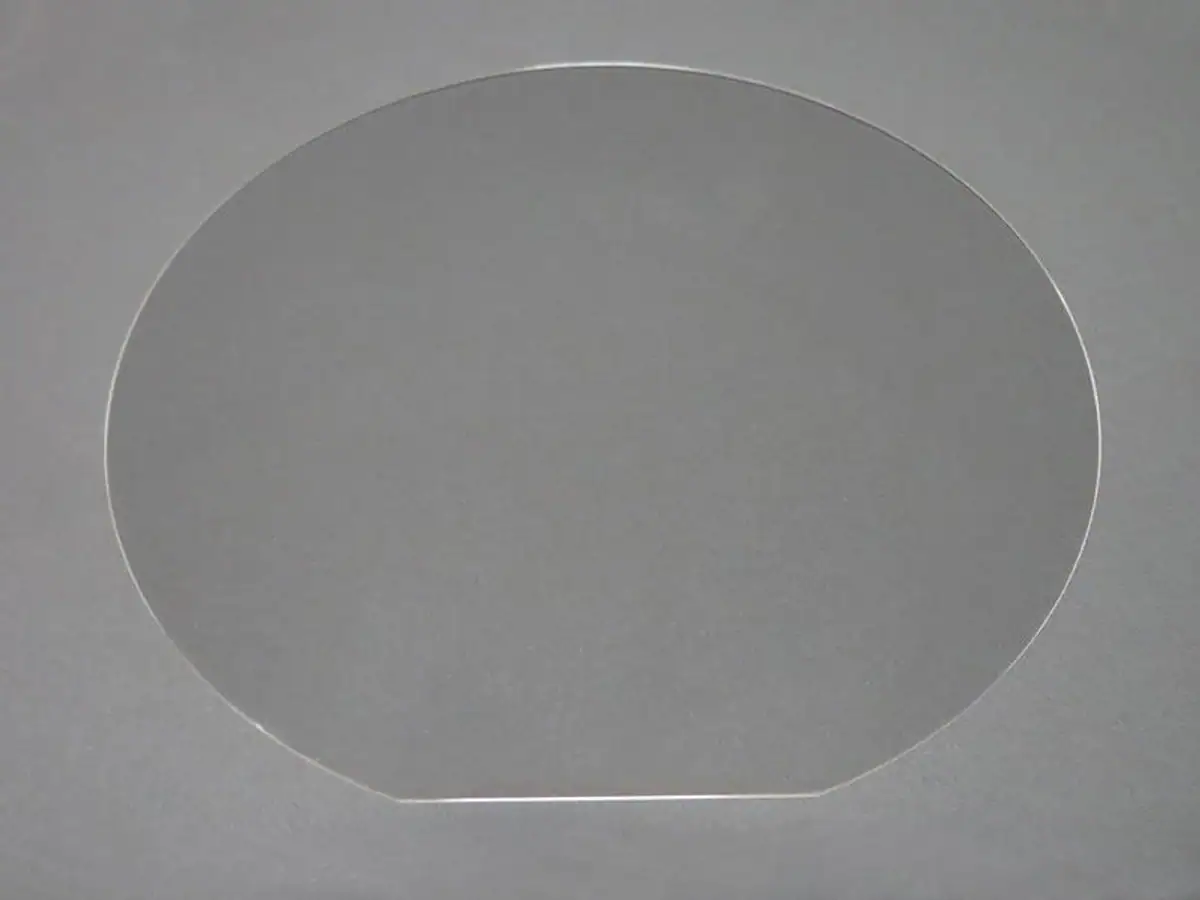
Circular blank with a straight reference flat
Example of a reference flat on a blank. Crystal orientation must be confirmed from the associated material record.

02 — Understand C, A and R without overreading the labels

The c-plane is perpendicular to the c-axis. The a-plane contains that axis, while the r-plane is inclined to it. These labels describe crystallographic geometry; they do not describe a grinder’s spindle arrangement or the finished optical curvature.

The distinction matters when a designer specifies optical behavior as well as mechanical dimensions. For example, propagation relative to the optic axis can matter to birefringence. The optical designer should choose the orientation required by the system rather than leaving that decision to the fastest shop-floor recipe.

Drawing or process itemWhat it tells the shopWhat it does not establish
C-, A- or R-plane designationOrientation of the specified surfaceA universal grinding speed
Orientation tolerancePermitted departure from the specified planeFinished surface-form tolerance
Flat or notch referenceA traceable direction if definedDirection if the reference is undocumented
Tool-feed directionEngagement relative to the partCrystal direction without a mapped reference

A sapphire crystal orientation diagram should show the axes and plane relationships clearly. It should not present an unverified force ranking as if it were part of the crystal definition.
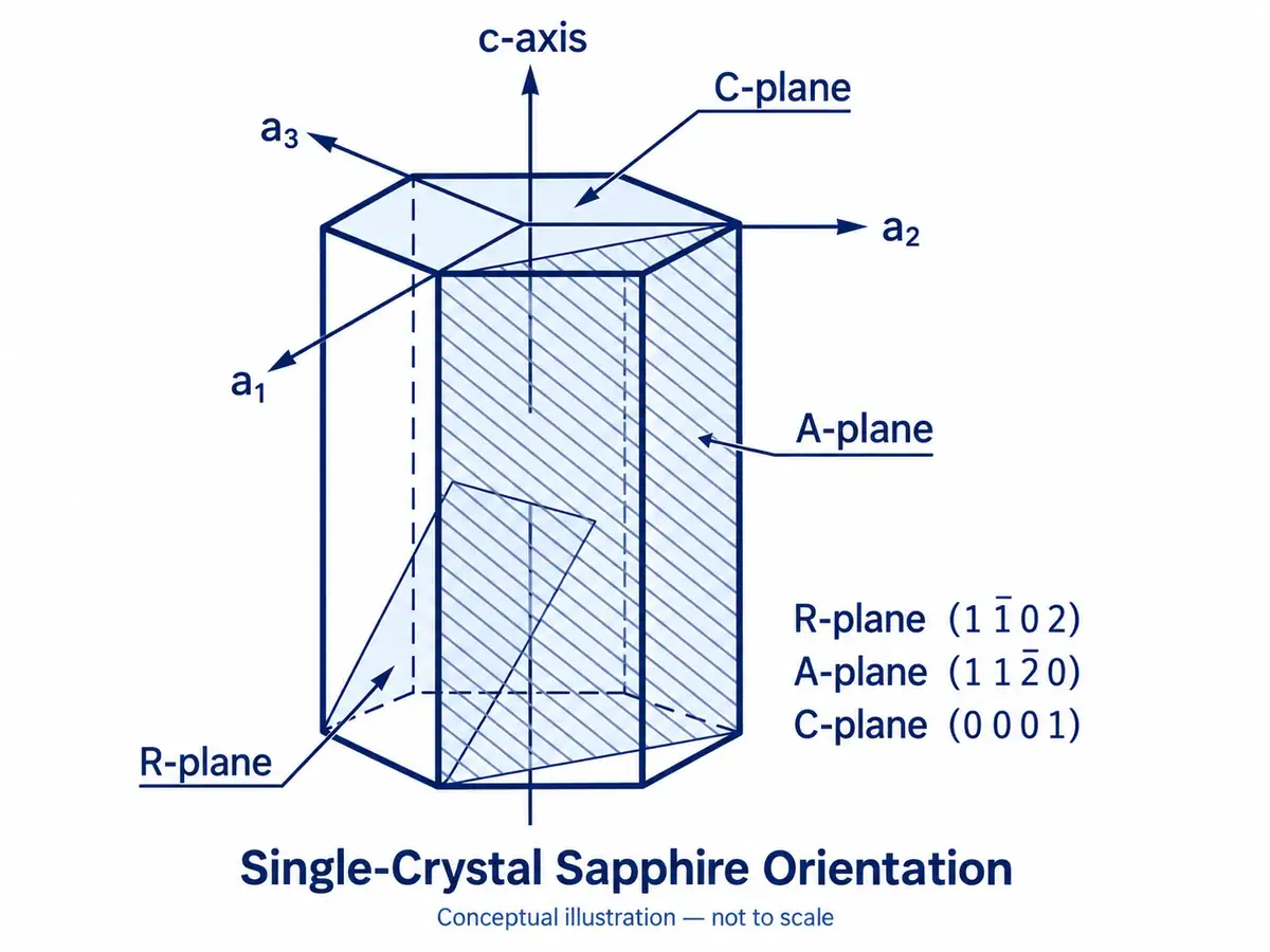
Sapphire crystal orientation diagram showing C A and R planes
Conceptual sapphire crystal-plane orientation diagram; not to scale.

03 — Separate crystallographic effects from process effects

Grinding response also depends on abrasive size, bond, wheel condition, engagement geometry, feed and support. A change in any of these can obscure the effect of orientation. Compare identified blanks under controlled conditions before deciding which variable caused the result.

Published experiments illustrate this boundary. A study of orthogonal grinding on prism-plane sapphire examines the relationship between grinding direction and surface characteristics. Its conditions should not be generalized into a shop-wide plane ranking.

Similarly, research on sapphire CMP anisotropy reports different polishing behavior with orientation and process chemistry. A result from chemical-mechanical polishing cannot be used directly as the removal rate for a different wheel-grinding operation.

Use sapphire crystal orientation to define test groups. Keep measured force, surface condition and final yield as separate outputs. A lower-force cut is not automatically the one producing the best finished optic.

04 — Edge damage needs a direction reference

A chip photograph becomes much more useful when it includes the tool-entry direction, crystal reference and finished-part boundary. Record where the damage occurs around the perimeter and whether it repeats after the blank is reoriented.

Distinguish exit breakout from damage introduced during unloading or tray handling. If the part has already passed through several operations, a damaged edge may not identify which operation caused it. Inspect at the handoff points and preserve part identity.

For sapphire crystal orientation trials, use a repeatable method to describe chip extent. Identify whether the defect lies outside the final diameter, within a chamfer allowance or inside a functional region. This prevents acceptable sacrificial-edge damage from being mixed with a finished-part rejection.

The existing sapphire wafer cutting discussion is an upstream starting point. Transfer the cut direction and inspection record to the grinding team rather than sending only the nominal blank dimensions.
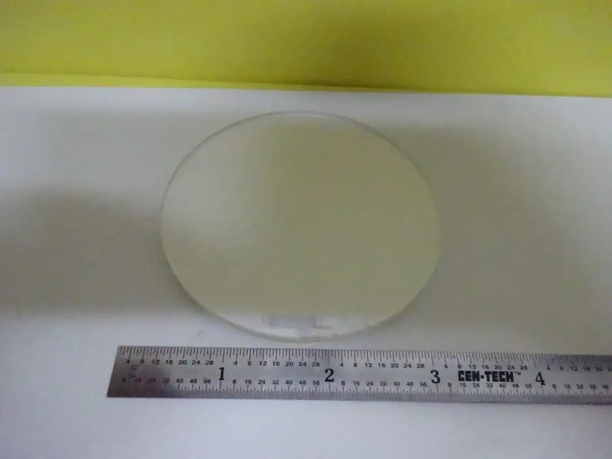
Circular sample placed beside a ruler
Sample overview for identification and handling review; this image does not resolve microscopic edge damage.

05 — Build a qualification table instead of copying parameters

Start from an approved machine and tooling range, then compare representative blanks systematically. Do not raise load just to make one orientation match another orientation’s cycle time.

Trial variableHold or recordEvaluation
Sapphire crystal orientationSupplier certificate and reference directionConfirm that the intended groups are actually different
Abrasive and bondSame qualified specification and known conditionCompare wear and cutting stability
Feed and engagementRecorded recipe within approved limitsCompare load trend and surface damage
Liquid deliveryDefined chemistry, flow condition and temperatureCheck repeatability throughout the cycle
WorkholdingSupport area and clamp or bond methodInspect after release
Final inspectionSame datum, aperture and measurement methodCompare accepted output, not appearance alone

Change a limited number of variables in each trial. Otherwise, a better result cannot be assigned to the new plane, a freshly dressed wheel or a slower feed. Retain the unsuccessful samples when useful; they mark the boundary of the qualified process window.

06 — Link cutting orientation to downstream stock

Cutting establishes more than thickness. It sets the blank’s orientation, edge condition and stock distribution for later processing. If those conditions vary without identification, the grinder may need extra stock simply to absorb uncertainty.

Discuss the required orientation and finished geometry when reviewing sapphire cutting equipment. The broader sapphire cutting solutions route can also connect blank preparation with the intended finishing process.

Do not assume that changing cutting direction will improve every downstream step. A change that helps slicing could complicate fixture loading or edge finishing. Compare the complete route and include losses after polishing and cleaning.

Carry sapphire crystal orientation into the work instruction alongside the material lot. If a batch is split among machines, preserve the reference rather than allowing each operator to choose an arbitrary presentation direction.

07 — Windows, watch crystals and substrates have different priorities

A window drawing may prioritize transmitted optical performance; a watch crystal may also require a specific edge appearance and case fit. A substrate specification may contain orientation requirements established by the customer’s downstream process. These applications cannot be reduced to one preferred plane.

For watch crystals, separate the optical designer’s orientation requirement from the edge-finishing recipe. A polished perimeter does not establish the transmitted wavefront, and a good face does not prove the chamfer will survive handling or assembly. The watch-glass process guide provides the application context.

When the customer permits more than one orientation, compare material availability, machining trials and final acceptance together. Do not select the cheapest incoming blank before calculating the rejected and reworked parts generated by the complete route.

Keep orientation markings away from surfaces that will become functional or be removed early. If a reference must be transferred to a carrier or tray, document the transfer and verify it before machining. A label that survives the route is useful only when its relationship to the part remains unambiguous.

08 — What to send with a sapphire enquiry

Include the material certificate, orientation and tolerance, a drawing showing the reference direction, and the finished geometry. State the required optical and edge-quality criteria separately. Add the proposed batch size and any existing process observations with identified samples.

If orientation is not yet specified, resolve it with the optical designer before treating the machining quote as final. Sapphire crystal orientation is part of the part definition, not a recipe field that a supplier should guess.

For an application review, send photographs with orientation marks visible and describe where in the route the defect first appears. That gives the cutting and finishing teams a common reference for a controlled trial.

Scroll to Top