Every CO₂ laser cutting head contains a set of zinc selenide optics that the laser beam passes through before hitting the workpiece. Those lenses, windows, and output couplers are consumables — they absorb a fraction of each pulse, accumulate contamination, and eventually fail. Laser system manufacturers who depend on a single external optics supplier for replacements are one supply chain disruption away from a production stoppage.
Building in-house CO₂ laser optics manufacturing capability changes that. It also changes your cost structure: a well-configured production line can produce ZnSe focus lenses at 30–50% of the cost of equivalent purchased optics at volume. The question is what equipment you actually need, in what sequence, and at what production scale the investment makes sense.
This guide covers CO₂ laser optics manufacturing equipment stage by stage — from raw CVD ZnSe blanks to finished, AR-coated lenses — with equipment specifications matched to three production scales.
Why ZnSe Dominates CO₂ Laser Optics Manufacturing
CO₂ lasers operate at 10.6 μm, a wavelength where ordinary optical glass is completely opaque. The material options for transmissive CO₂ laser optics are limited: ZnSe, ZnS, and germanium for the infrared range, with ZnSe dominant for transmission components because it combines the lowest absorption at 10.6 μm with a refractive index high enough for compact lens designs.
Laser-grade CVD ZnSe achieves bulk absorption below 0.0005 cm⁻¹ at 10.6 μm — meaning a 10 mm thick lens absorbs less than 0.5% of incident energy per pass. This low absorption is what allows ZnSe focus lenses to survive sustained kilowatt-class CO₂ beams without thermal runaway. Germanium, by comparison, has roughly 40× higher absorption and cannot be used for high-power transmission optics.
The consequence for CO₂ laser optics manufacturing equipment choices: everything in your production line must be optimized for ZnSe’s specific combination of properties — soft, brittle, and mildly toxic in particulate form. Equipment that performs well for glass or germanium often requires parameter modification for ZnSe.
CO2 Laser Optics Manufacturing Equipment: The Four-Stage Chain
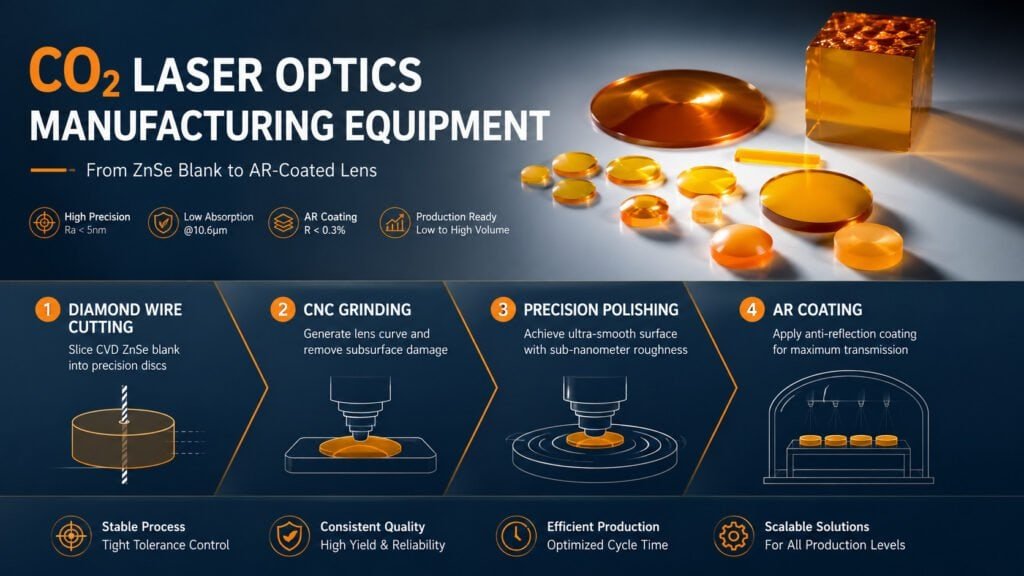
A complete CO₂ laser optics production line covers four processing stages. Each stage has specific equipment requirements, and the output quality of each stage sets the input condition for the next.
| Stage | Process | Equipment Type | Output Specification |
|---|---|---|---|
| 1 | Blank cutting | Diamond wire saw | Ra 0.6–1.5 μm, TTV < 15 μm |
| 2 | Curve generation + grinding | CNC spherical grinder | Ra 0.1–0.3 μm, sagittal height ±0.5% |
| 3 | Polishing | Precision polishing system | Ra < 5 nm, surface figure λ/4 P-V |
| 4 | AR coating | Vacuum deposition system | Reflectance < 0.3% at 10.6 μm |
The quality gate between stages determines your overall yield. A blank that exits cutting with Ra 2.0 μm instead of 0.8 μm requires two additional grinding passes to reach the polishing input specification — adding cycle time and increasing subsurface damage risk.
Stage 1 CO2 Laser Optics Manufacturing Equipment: Blank Cutting
CVD ZnSe is grown as large boules, typically 150–300 mm diameter cylinders. The first manufacturing step slices these boules into lens-diameter discs at the target thickness plus grinding and polishing stock.
Diamond wire sawing is the appropriate cutting technology for ZnSe. The wire contacts the material along a narrow line, distributes cutting force along the wire length, and maintains continuous coolant flow to prevent heat buildup at the cut interface. For ZnSe specifically, three cutting parameters require adjustment from glass or germanium settings:
Feed rate: 3–6 mm/min for ZnSe, compared to 8–12 mm/min for optical glass at the same wire diameter. ZnSe’s low fracture toughness means aggressive feed rates produce edge chips and subsurface cracks that require extra grinding passes.
Wire diameter: 0.35–0.50 mm for most CO₂ laser optics. Finer wire (0.25 mm) reduces kerf loss but requires lower feed rate and higher tension control precision.
Coolant: White mineral oil, not water-based fluids. ZnSe can develop surface staining in contact with water-based coolants, and the staining is difficult to remove before grinding.
Our ZnSe lens cutting machine and SGSM-40 oscillating wire glass slicer handle ZnSe blanks up to 300 mm diameter with servo-controlled tension systems that maintain consistent wire force through the full cut depth.
Stage 2 CO2 Laser Optics Manufacturing Equipment: Grinding
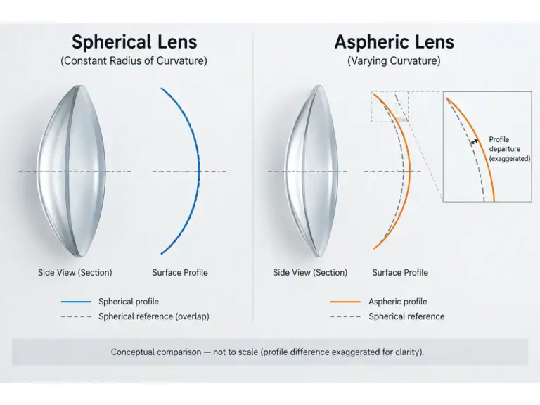
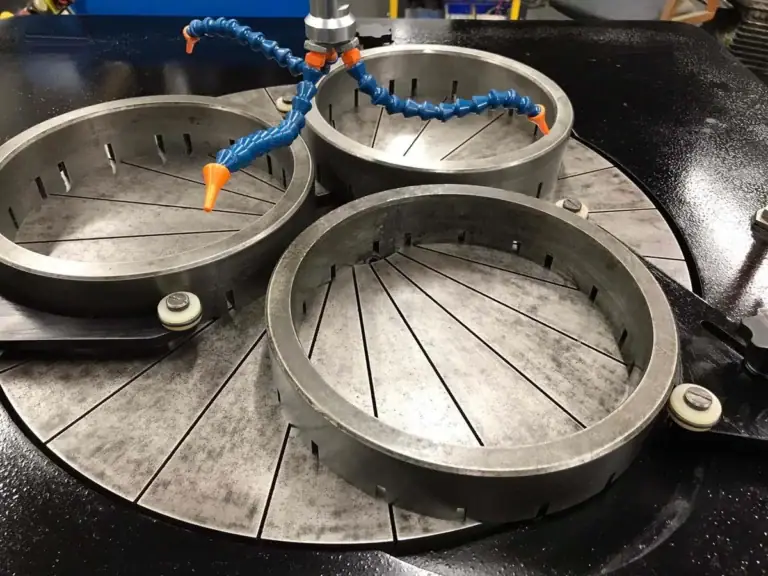
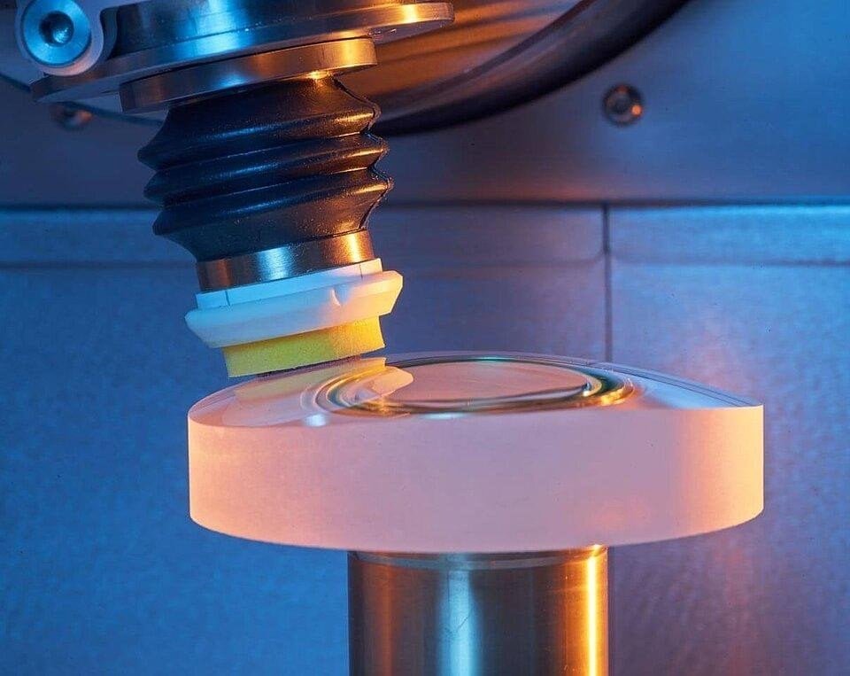
Grinding serves two functions in CO₂ laser optics manufacturing: it generates the lens curvature (spherical or aspheric) and removes the subsurface damage layer left by cutting. Both functions must be accomplished simultaneously — a machine that generates good curvature but leaves deep subsurface damage will produce polishing failures downstream.
For ZnSe CO₂ laser optics, grinding wheel selection matters more than for harder materials:
Rough generation: D46–D91 diamond wheels, resin or metal bond. ZnSe grinds faster than germanium at the same parameters — reduce infeed rate by 30–40% compared to germanium settings to maintain equivalent surface quality.
Finish grinding: D7–D15 diamond wheels, resin bond. ZnSe’s softness means fine grit removes material quickly; reduce pass depth to 2–3 μm for finish grinding passes.
A common mistake with ZnSe is applying the same grinding parameters used for optical glass. Glass and ZnSe have similar hardness (ZnSe Knoop ~120, BK7 Knoop ~600) — wait, ZnSe is actually softer than glass. Treating ZnSe with glass parameters produces over-cut surfaces that require extra polishing stock removal.
Spindle runout specification for ZnSe grinding should be ≤ 1 μm TIR. Higher runout produces a rippled surface that manifests as a high-spatial-frequency waviness that polishing cannot fully remove within normal polishing stock limits.
Stage 3 CO2 Laser Optics Manufacturing Equipment: Polishing
Polishing is where CO₂ laser optics either reach laser-grade surface quality or fail. The target for high-power CO₂ laser ZnSe focus lenses — Ra < 5 nm, surface figure λ/4 P-V, scratch-dig 40-20 — requires a polishing system with pressure control accurate to ±0.5 kPa, temperature-stabilized slurry delivery, and programmable lap speed profiles.
ZnSe polishing uses finer abrasives and lower pressure than germanium:
| Polishing Stage | Abrasive | Concentration | Pressure | Material Removal Rate |
|---|---|---|---|---|
| Rough polish | 1 μm alumina | 5–10% | 3–5 kPa | 0.5–1.0 μm/min |
| Semi-fine polish | 0.5 μm diamond | 2–5% | 2–4 kPa | 0.2–0.5 μm/min |
| Final polish | 0.1 μm diamond or colloidal silica | 1–3% | 1–3 kPa | 0.05–0.1 μm/min |
The pressure values above are 40–60% lower than the equivalent stages for germanium polishing. Applying germanium polishing pressure to ZnSe produces orange peel texture — a grain-boundary artifact visible under oblique illumination — that fails interferometric inspection and requires returning to semi-fine polishing to remove.
For CO₂ laser optics at production volumes, the polishing system also needs sealed slurry circulation and HEPA-filtered exhaust to contain selenium particulate. Our zinc selenide optics polishing system integrates closed-loop slurry management with automated pressure profiling across the polishing cycle.
Stage 4: AR Coating for CO₂ Laser Optics
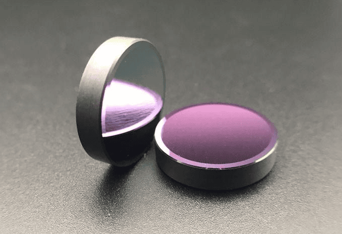
Uncoated ZnSe reflects approximately 17% of incident 10.6 μm radiation per surface. For a focus lens with two surfaces, that means 32% of the laser power is reflected rather than transmitted — creating back-reflections and reducing delivery efficiency. AR coating brings per-surface reflectance below 0.3% for the 10.6 μm band.
CO₂ laser AR coating is typically a multi-layer thin film stack deposited by electron beam evaporation or ion-assisted deposition. The coating equipment required:
- Vacuum chamber: minimum 10⁻⁵ Torr base pressure; better than 10⁻⁶ Torr for high-power applications
- Substrate heating: 100–200°C during deposition for adhesion
- Thickness monitoring: quartz crystal microbalance with ±0.5 nm layer control
- Batch capacity: 50–200 lenses per run depending on lens size
High-power CO₂ laser applications (> 2 kW average power) require coating qualification against laser damage thresholds, typically per ISO 21254. A coating with nominal 0.2% reflectance that has pinhole defects or absorption anomalies can fail catastrophically at power densities that the bulk coating would survive.
Matching CO2 Laser Optics Manufacturing Equipment to Production Scale
Equipment investment and configuration depend on your volume target. Three reference configurations:
Low volume (< 200 lenses/month):
- Single diamond wire saw handling all blank cutting
- One CNC grinder with wheel change between rough and finish stages
- One polishing machine running sequential abrasive programs
- External coating or small in-house batch coater
- Estimated floor space: 40–60 m²
Medium volume (200–1,000 lenses/month):
- Dedicated cutting machine with servo tension control
- Two grinding machines (rough and finish dedicated)
- Two polishing machines for parallel processing
- In-house batch coater, 100+ lens capacity
- Estimated floor space: 80–120 m²
High volume (1,000+ lenses/month):
- Multiple cutting and grinding machines with robotic transfer
- Polishing machines with automated recipe control
- High-capacity coater with multiple deposition sources
- In-line metrology for non-contact radius and thickness measurement
- Estimated floor space: 200+ m²
The transition from low to medium volume is typically triggered by polishing becoming the throughput bottleneck — one polishing machine can process 50–80 lenses per shift, and adding a second machine often doubles throughput without requiring additional support equipment.
Quality Verification Equipment
CO₂ laser optics manufacturing equipment for production includes not just processing machines but also metrology:
- White light interferometer: surface roughness Ra, waviness, and form error measurement. Required at incoming inspection and after polishing.
- Radius measurement bench: sagittal height or radius of curvature confirmation after grinding.
- Spectrophotometer: AR coating transmission measurement at 10.6 μm. Required for every production batch.
- Laser calorimeter: bulk absorption measurement for laser-grade material qualification (sample basis).
For the complete equipment chain covering infrared optics manufacturing — from ZnSe and germanium cutting through grinding, polishing, and quality verification — our equipment solutions are configured for production-scale CO₂ laser optics from the start.
According to the Laser Institute of America’s industrial laser market analysis, CO₂ laser installations in cutting, welding, and marking applications continued growing through 2025, with optics replacement representing a recurring revenue stream for equipment suppliers. Manufacturers who bring CO₂ laser optics production in-house capture this recurring margin rather than paying it to third-party optics vendors. The SPIE Handbook of Optics provides the material and coating specification reference for CO₂ laser optics qualification.
For a detailed process breakdown of ZnSe component manufacturing, see our ZnSe CO₂ laser optics manufacturing guide. For focus lens-specific manufacturing details, see ZnSe focus lens manufacturing.