
ZnSe wafer cutting from zero experience: square blocks, round rods, one open table
The customer had never machined optical material before. Their stock came in two shapes, and any saw that dictated a workpiece geometry was disqualified on day one. This file covers the platform decision — and the process plan we shipped with it.
Why does ZnSe wafer cutting punish shape-specific saws?
ZnSe wafer cutting starts with a materials-handling fact most saw brochures skip: zinc selenide rarely arrives in one convenient geometry. This customer's incoming stock split between square and rectangular blocks on one side and cylindrical rods on the other — all of it destined to become wafers for infrared optics. A machine built around a round-bar chuck handles the rods and rejects the blocks; a vise-and-fence setup handles the blocks and fumbles the rods. Buying shape-specific saws would have meant buying the plant twice.
The material raises the stakes further. Zinc selenide is soft by optical-crystal standards — a Knoop hardness around 105–120, far below germanium or sapphire — and brittle with it, so clamping force itself is a defect source. Squeeze a ZnSe block hard enough to trust a mechanical clamp and you may have already cracked the wafer you were trying to cut. The right answer is a machine that neither dictates the workpiece shape nor grips it by force.
An open table that does not ask what shape you brought
The SG-series endless diamond wire saws answer the shape problem structurally. The load table is open: a flat worktable with YZ servo axes moving the workpiece through a continuously circulating diamond wire loop. There is no chuck geometry to match, no fence to square against, no jaw profile to fit. If the workpiece fits inside the working envelope — 200 × 200 mm on the SG 20, 400 × 400 × 400 mm on the SG 40 — it can be cut. Blocks, rods, offcuts, and remnants all mount the same way: bonded to a sacrificial carrier plate that sits on the table.
That mounting method is the second half of the answer. Adhesive fixturing spreads the holding load across the whole bonded face, so the soft ZnSe sees no point clamping force at all. The wire then does what an endless loop does on brittle material: one direction of travel, constant tension, kerf equal to wire diameter, and a cut face with no blade reversal marks. In ZnSe wafer cutting that face is the entire downstream budget — every micron of as-cut quality is a micron the grinding stage does not have to buy back.
What does a first-time processor actually need?
This customer had no machining history — no fixturing habits to unlearn, but also no baseline to start from. A saw shipment alone would have left them qualifying a process from scratch on expensive material. So the scope of supply was the process, with the machines inside it:
- Fixturing method. How to bond blocks and rods to the carrier plate — adhesive choice, bonding pattern, and cure practice — so soft ZnSe is held over its full face instead of squeezed at points.
- Cutting parameters. Starting feed rate and wire linear speed for their zinc selenide grades, established by test cuts on their own material rather than copied from a generic table, then handed over as written settings.
- De-bonding. How to release finished wafers from the carrier plate after the cut without edge damage — the step first-time shops most often improvise, and the step where a clean wafer is easiest to ruin.
- Downstream grinding plan. A matched plan for the grinding stage that follows, sized to the as-cut surface the wire delivers, so the wafers leave the saw with a known, budgeted allowance instead of a guess.
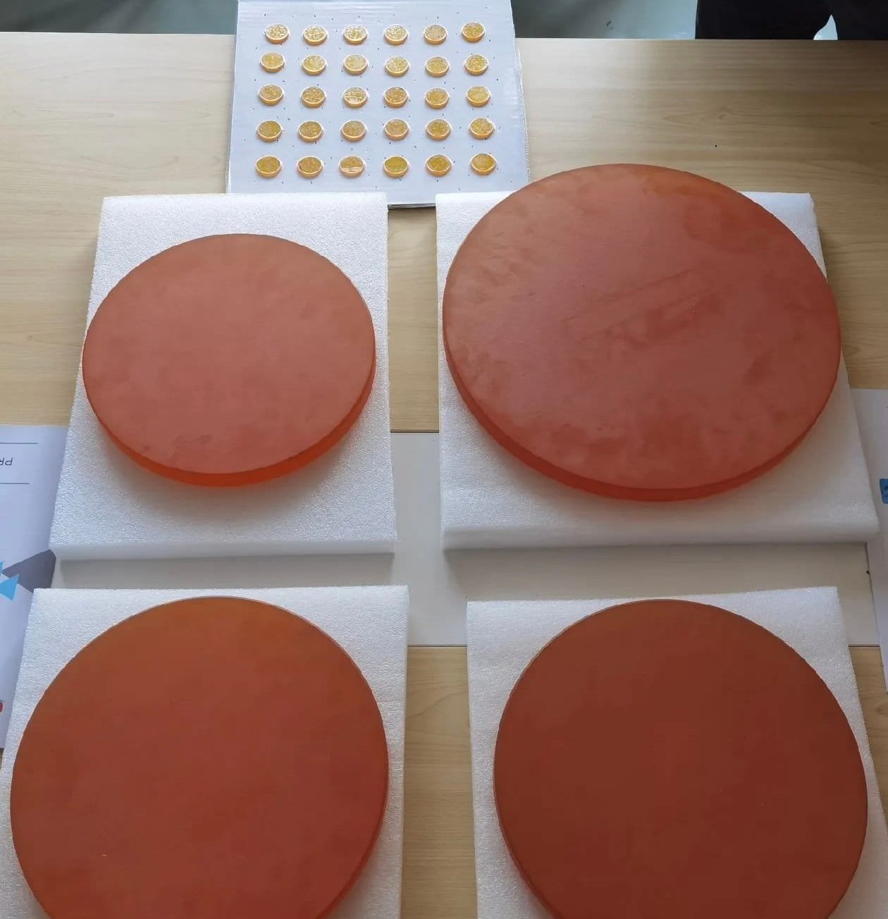
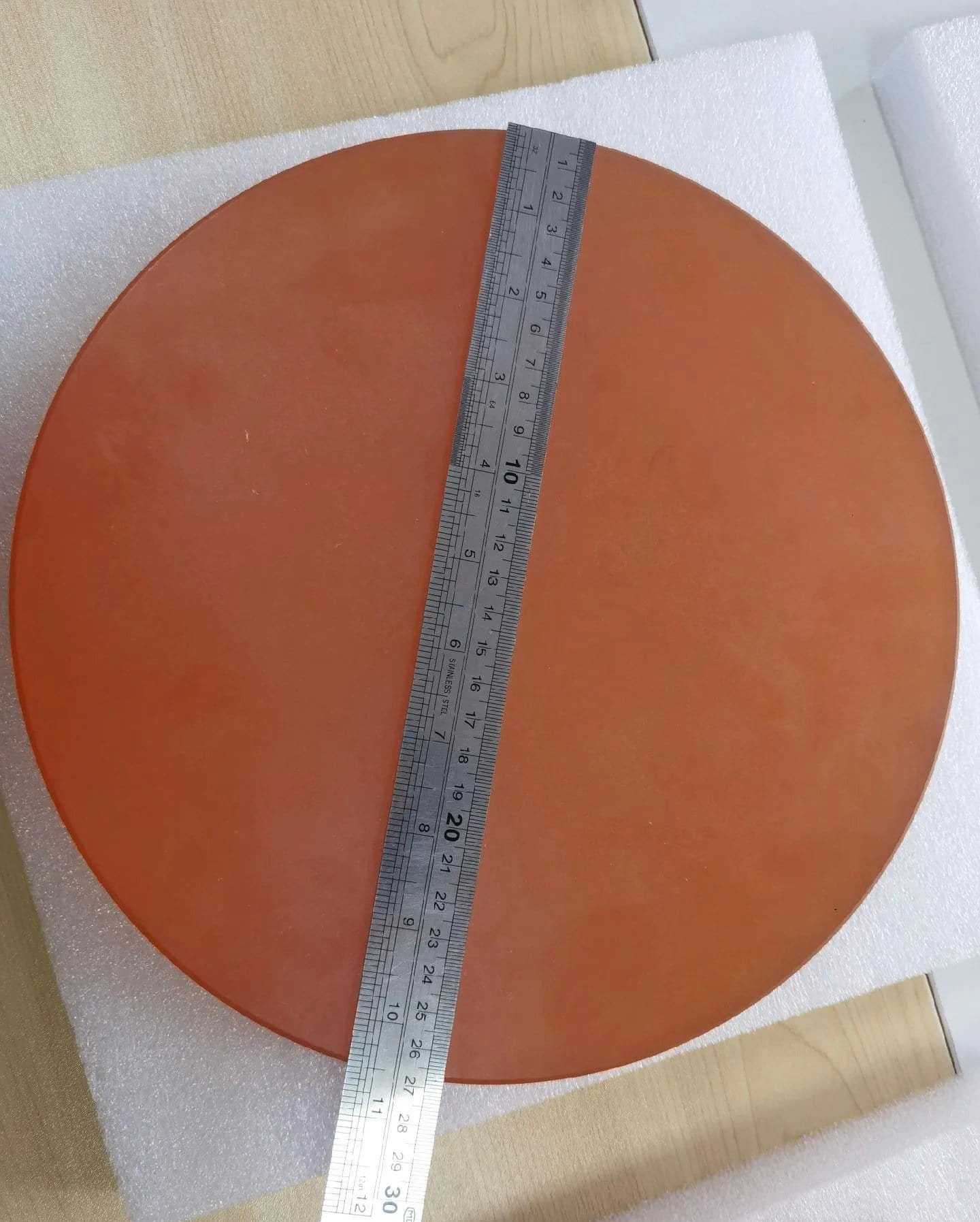
The cut-face quality is what makes that last handoff calm. The photographs below are the customer's ZnSe wafer cutting results as they came off the wire — uniform faces, edges intact, ready for a grinding allowance planned in advance.
Four models, one fixturing philosophy
The final purchase was not one machine but a small fleet, sized to the spread of their stock and the jobs behind it:
| Model | Role in this plant |
|---|---|
| SG 20 | Compact slicing station for smaller blocks and rods — the volume workhorse for standard wafers |
| SG 40 | Large-envelope slicing up to 400 mm workpieces — takes the biggest blocks without sectioning them first |
| SGI 20 | Adds the contour-cutting system: CAD-programmed profiles from DXF for shaped parts beyond plain wafers |
| SGR 20 | Adds a rotary axis for round-part work, extending the same wire platform to rotational cuts |
One consequence matters operationally: ZnSe wafer cutting runs the same way on all four machines — the fleet shares one open-table logic, the same carrier-plate fixturing, and the same wire consumables family. An operator trained on the SG 20 is functional on the SG 40 the same week, and the process documents written in § 03 apply across the line with envelope-specific numbers, not four separate methodologies.
Where this file sits in the toolchain
This is the third slicing-and-shaping case on this platform family: germanium puck slicing documented the unattended-batch economics, the irregular germanium lens cutting file documented the contour system, and this one documents shape-agnostic fixturing on a new material. Readers evaluating ZnSe specifically should also see the dedicated ZnSe lens cutting machine page for equipment detail, and the wider infrared optics processing equipment range for the grinding and polishing stations the § 03 plan hands over to.
For ZnSe polishing dust, mist, slurry, and maintenance considerations, see our ZnSe polishing dust, mist, slurry and maintenance guide.
If you have ZnSe on the floor and no process on paper, that is the exact starting condition of this file. Send your block and rod dimensions with target wafer thicknesses; we cut your sample material, and the ZnSe wafer cutting parameters that worked ship back with the quote — fixturing, settings, and de-bonding included.
Send material dimensions and wafer targets to daria@endlesswiresaw.com for a test-cut and process plan.