Wire Saw Marks: How Much Stock Grinding Must Remove
A cut face can look uniform under workshop lighting and still contain a groove that survives the first grinding pass. Another face may look rougher yet clean up with less stock removal. Wire saw marks are useful process evidence, but appearance alone cannot determine the finishing allowance.
The correct removal budget combines measured surface form, the deepest relevant surface defects and a qualified assessment of subsurface damage. These quantities must share a defined datum. Do not simply add the peak-to-valley height to an assumed damage multiplier. That can either double-count stock or leave cracks behind.
01 — Read wire saw marks before changing the feed
Start by separating repeated bands from isolated events. Regular stripes may correspond to a recurring motion, a rotating component or a changing wire condition. Random pits, short scratches and edge breakouts require a different investigation. Photograph both faces with the cutting direction and part identification visible.
Clean the part using the approved material-specific procedure before inspection. Adhered abrasive and dried residue can resemble damage. Keep the inspection lighting, magnification and viewing angle consistent so a change in the photograph does not become a false process improvement.
A useful first record links the position of each feature to the cut sequence. Note whether the feature begins at entry, appears halfway through the cut or worsens near exit. Also record support, bonding, wire history and interruptions. Our optical cutting quality guide places these observations alongside dimensional acceptance.
02 — Separate process clues from proven causes
Wire saw marks do not identify a failed component by themselves. Use their pattern to choose the next controlled check, then change one variable at a time.
| Observed feature | Candidate checks | Evidence needed before changing the recipe |
|---|---|---|
| Repeated bands across a face | Guide condition, periodic motion, feed interruptions | Position or time correlation over several cuts |
| Strong entry or exit damage | Support stiffness, engagement and breakout geometry | Comparison of entry and exit on identified samples |
| Isolated deep scratch | Loose debris, abrasive condition, contamination | Cleaned surface inspection and consumable history |
| Broad face bow | Cutting load, support, thermal condition and release | Face-form measurement after unclamping |
| Different results on opposite faces | Cut sequence, local support and stock condition | Matched measurements using the same datum |
Wire diameter, abrasive size and feed interact. A thinner wire does not automatically leave shallower defects, and increasing tension without checking the machine specification can create a different problem. Use the wire-loop tension and strength discussion as a starting point for the configuration review, not as permission to exceed an approved operating range.
03 — Measure the surface with a stated filter and datum
For wire saw marks, a single roughness number is incomplete. A profile across the cutting direction can reveal features that a parallel trace misses. An areal measurement can show whether a groove is isolated or continues across the usable aperture.
Record instrument type, stylus or optical configuration, sampling interval, evaluation length and filtering. Separate overall bow from shorter-wavelength texture. If two reports use different filters, their roughness values may not describe the same physical features.
Identify the deepest defect that matters inside the finished part boundary. A valley outside the final diameter may disappear during edging. One inside the clear aperture needs an explicit removal or rejection decision. Do not choose a measurement location merely because it produces the cleanest profile.
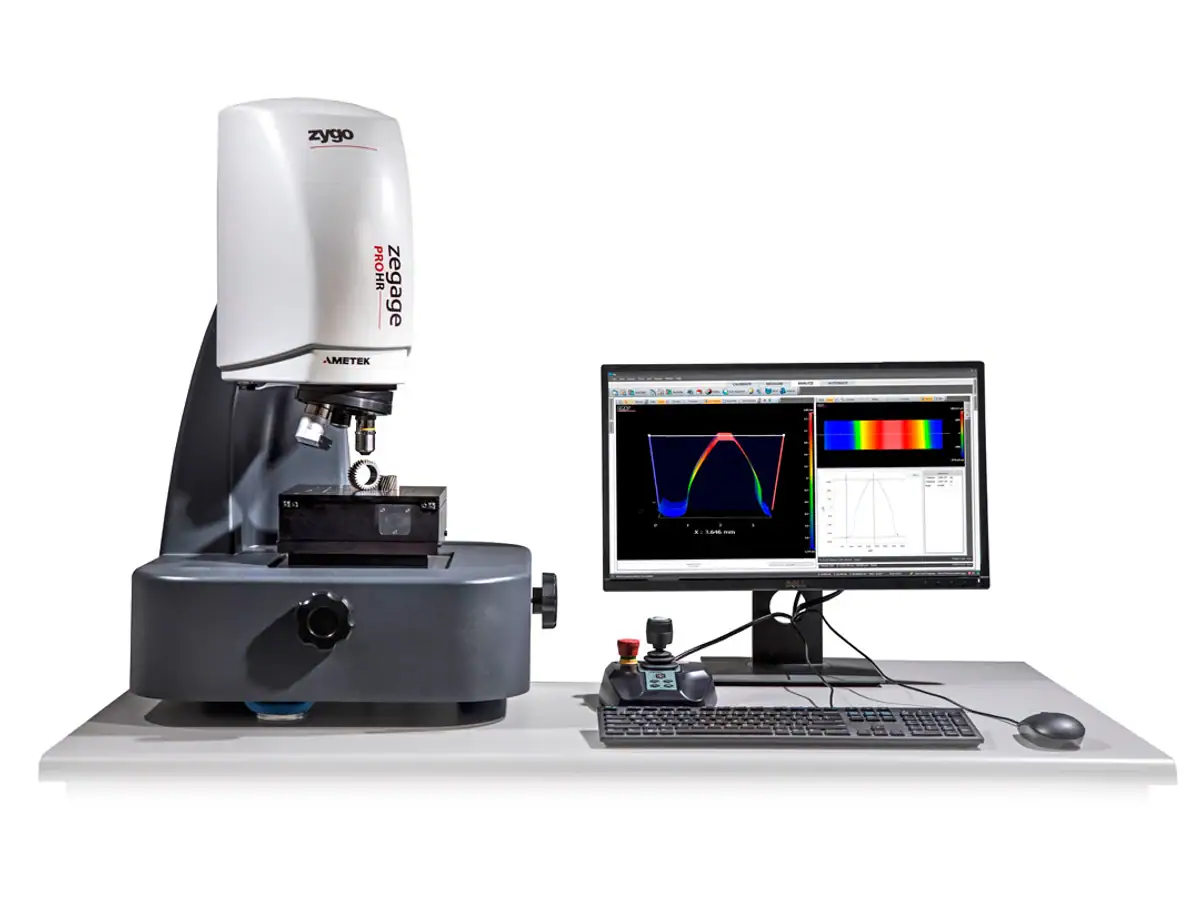
Before using a scan to set stock, compare repeat measurements and inspect an accessible reference. Transparent and steep surfaces can challenge optical instruments; contact methods introduce their own access and loading limitations. An unreadable region is missing evidence, not a zero-depth result.
04 — The crack layer has a different boundary
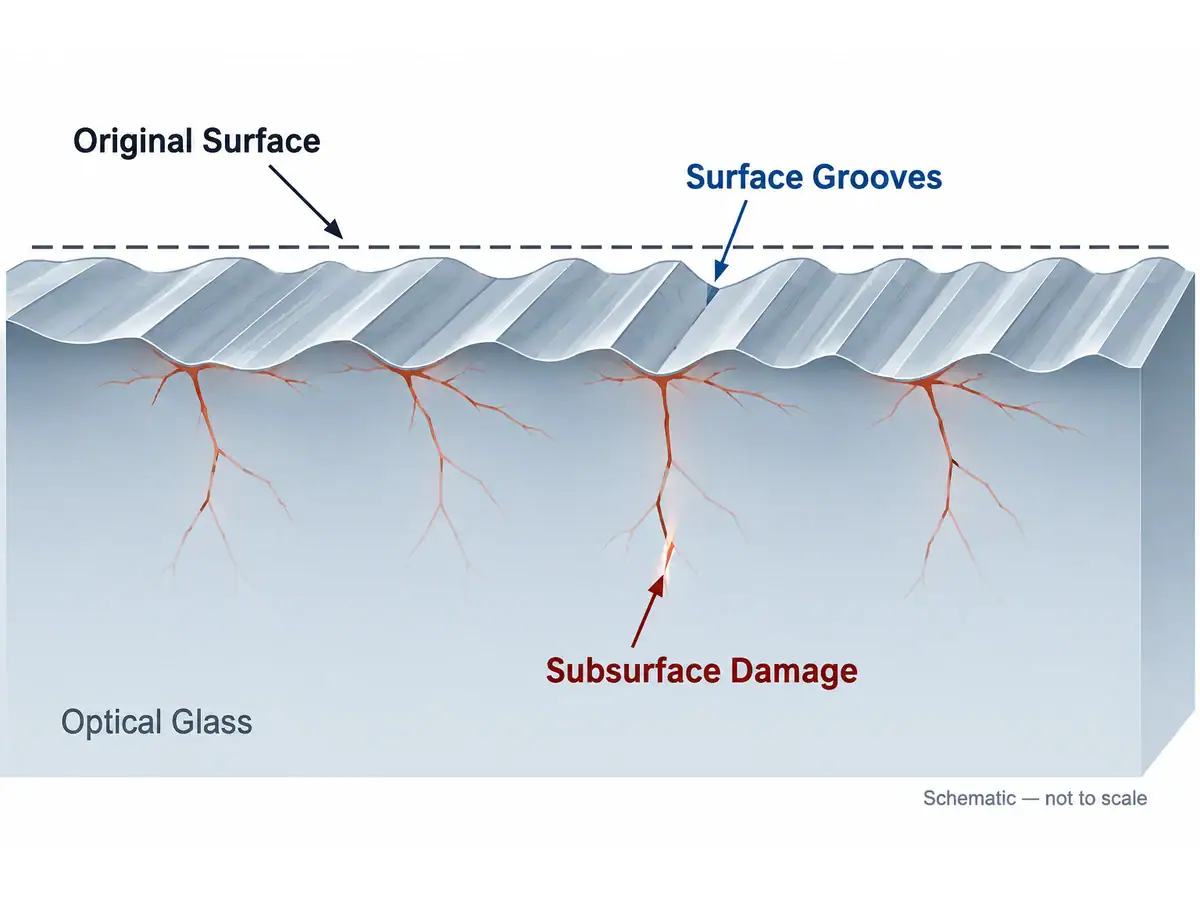
The visible valley of wire saw marks is not necessarily the deepest affected material. Cracks can extend below the apparent surface. Conversely, an assumed fixed multiplier can overstate damage when applied to a different material, abrasive or cutting mechanism.
Hed and Edwards’ optical-glass grinding study reports a relationship between roughness and damage under its investigated conditions. It does not establish a universal two-times or three-times rule for diamond-wire-cut germanium, ZnSe or sapphire.
Treat damage depth as a process qualification question. The subsurface-damage guide explains why a polished appearance cannot by itself prove that the earlier crack layer has been removed. When setting the roughing budget, define whether a reported depth is measured from a nominal face, a local peak or a local valley.
05 — Qualify damage using representative sacrificial samples
A laboratory can examine a prepared cross-section or a shallow taper through the damaged region. A taper spreads a small depth over a longer lateral distance, which can make the damage boundary easier to observe. Preparation must avoid introducing cracks that are then mistaken for cutting damage.
In a simplified planar taper, vertical depth corresponds to lateral distance multiplied by the tangent of the measured taper angle. This geometric relationship is not a complete test method: the original surface reference, angle calibration and identification of actual cracks still matter.
Chemical revelation may improve crack visibility for some material and method combinations, but chemistry cannot be transferred casually between optical glass and infrared materials. Use a qualified laboratory procedure, with its material-specific safety controls, rather than an improvised shop-floor etch.
For wire saw marks qualification, include samples from more than the best section of the batch. Keep the destructive examination tied to the original cut record. A photograph without a sample number cannot support a repeatable production allowance.
06 — Material changes what to investigate
Avoid ranking all optical materials by a single assumed damage depth. Stock geometry, crystal direction, tooling and support can change the result within one material family.
| Material | Investigation priority | Decision supported |
|---|---|---|
| Germanium | Surface form, breakout and downstream cleanup | Whether more usable parts survive the complete route |
| ZnSe | Support, handling damage and controlled wet processing | Whether the cutting and cleaning sequence is suitable |
| Sapphire | Orientation, direction of engagement and edge condition | Whether the recipe transfers between specified blanks |
| Optical glass | Exact grade, abrasive history and crack assessment | Whether the qualified allowance covers that glass |
The point of this table is to organize trials. It does not supply a material-specific depth guarantee. Comparing wire saw marks across materials is meaningful only when the measurement definitions and finished-part requirements are also recorded.
07 — Carry the result into the grinding allowance
Map the finished geometry inside the measured blank. The planned roughing removal must cover shape correction and the qualified damage boundary while leaving the stock required for subsequent fine grinding and polishing.
Do not count the same crack layer twice: once inside the established roughing removal and again as a separate safety allowance. Equally, do not assume that removing a visible groove has removed every underlying crack. The cutting allowance calculation keeps the per-face stock budget separate from kerf consumption.
Discuss this handoff when selecting optical lens grinding equipment. The useful question is whether the incoming blank can reach its finished geometry consistently, not whether a machine can remove a conspicuous stripe quickly.
08 — Close the trial with a repeatable release rule
A production release record should identify the allowable incoming form, the inspection method, the demonstrated removal sequence and the conditions requiring requalification. Include wire changes, a new material grade, altered support and a significant recipe change among the review triggers.
Keep rejected samples as evidence when practical. They show where the process boundary lies and prevent a later operator from repeating an unsuccessful setting. Review results after deblocking and final inspection, because a good result while clamped may conceal a later dimensional problem.
Send the drawing, material, cut direction and photographs of the wire saw marks when you request free sample cutting. Use the trial to establish the as-cut condition; agree any grinding or polishing validation separately.