
Double Side Lapping Machine
A double side lapping machine works both faces of a whole batch at once, between two counter-rotating plates, under one load the machine holds as a number. Parts to Ø395 mm, 0.3 to 30 mm thick.
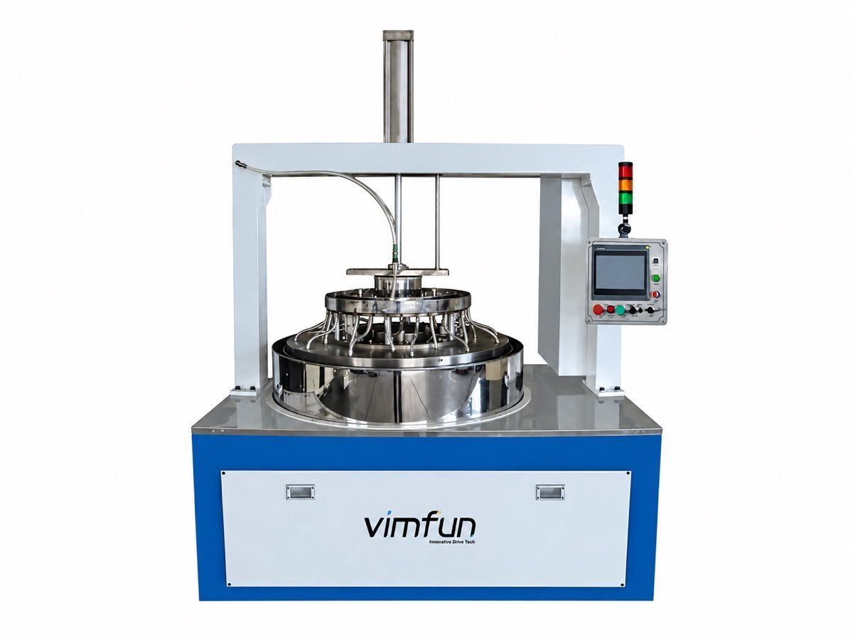
A batch machine, not a part machine
On a swing polisher each spindle holds one part and gives it its own pressure, its own stroke and its own tool. An operator can lean on one part and go easy on the next. Fifty parts is fifty small decisions, and fifty chances for them to come out different.
Lapping inverts that. Twenty, fifty, eighty parts ride in planetary carriers between an upper and a lower plate. They all see the same two plates, the same slurry and the same load. No part can be favoured and none can be neglected. Thickness consistency and parallelism stop being something a person holds and become a property of the run — which is the whole idea a double side lapping machine is built around.
That difference decides which machine belongs on the quotation. If the requirement reads this element must hit R120 with a 3.2 mm centre thickness, it is per-part work for the swing machines on the polishing range. If it reads these 240 windows must agree with one another and each be parallel to within a few arc-seconds, it is batch work, and no amount of per-part care gets there at a sane cost.
A per-part machine makes one part right. A lapping machine makes a batch agree.
How does the machine keep both faces parallel?
Three motions and one pressure. Nothing in the geometry is clever; what makes it work is that no part in the machine gets a privileged position on the plate.
Every carrier in a double side lapping machine is a thin disc with pin teeth cut round its edge. It meshes with a sun gear at the centre of the machine and with a ring gear around the outside. Drive the sun and the ring at different speeds and the carrier does two things at once: it orbits the machine’s centre and it spins about its own. The parts riding in its pockets never repeat a path across the plate, so the plate wears evenly and every part sees, over a cycle, the same amount of it.
Counter-rotating plates
Upper and lower plates turn opposite ways, each on its own inverter drive, each reversible. What wears one plate toward the rim wears the other toward the centre, so the pair stays flat longer than either would alone.
Load set as a number
Working pressure is set on an electro-pneumatic proportional valve and held there. The upper plate drops fast to just above the work and then slowly onto it — which is what stops a 0.3 mm substrate being cracked at the moment of contact.
The recipe, not the operator
Eight parameter segments and ten stored recipes run from the touchscreen under PLC control, so speed, load and time change through the cycle to a programme. A double side lapping machine earns its money on the tenth run, not the first.

How are TTV, parallelism and flatness actually measured?
This is the question that decides whether a lapping order runs smoothly, and the one most datasheets skip. Three figures get quoted on a double side lapping machine enquiry, they are measured three different ways, and only two of them mean anything on a part straight off the lap.
- Thickness and TTV — a contact gauge on a granite stand, five points per part: the centre and four near the rim at ninety degrees. Total thickness variation is the largest of those five minus the smallest. On transparent parts a chromatic confocal or spectral-reflectance probe does the same job without touching the surface.
- Parallelism, or wedge — the same five-point map gives it. Quote it either as a thickness difference across the diameter or as an angle, and say which: the two numbers are not interchangeable, and a drawing that mixes them is an argument waiting to happen.
- Flatness — interferometry against a reference flat, read in fringes at 632.8 nm and interpreted the way ISO 14999-4 sets out. A lapped surface scatters too much to read that way. Flatness is a figure you take after polishing, which is why a sensible lapping specification is written in TTV and parallelism and leaves fringes to the next station.
What the machine holds is plate condition, load and cycle — not a closed-loop reading on each part. Nothing gauges the batch in process. So write acceptance as a batch statistic measured on your own equipment at a stated temperature, say thirty parts sampled from the carrier set all inside a given TTV, rather than as a number the machine is supposed to display. We run your parts and send the measured map with the quotation.
What goes in the carriers
The platform came out of semiconductor work and still does it. In an optical shop it takes on the flat work that swing polishers are poor at.
Optical and reference flats, windows, filter and wave-plate substrates, sapphire and quartz-crystal blanks, fused silica discs, technical ceramic plates — alongside the silicon, gallium arsenide and ceramic substrates the machine was originally built for. Anything flat, hard and brittle, in a batch.
Size is the real limit, not material. A double side lapping machine in this range takes parts to Ø290 or Ø395 mm and 0.3 to 30 mm thick. Small parts go many to a carrier and large ones one to a carrier, and the pocket set is cut for your part — it is tooling, quoted with the machine, not a universal accessory. Materials from optical glass through sapphire all lap on the same principle; what changes is the abrasive, the plate material and how gently the upper plate has to land.

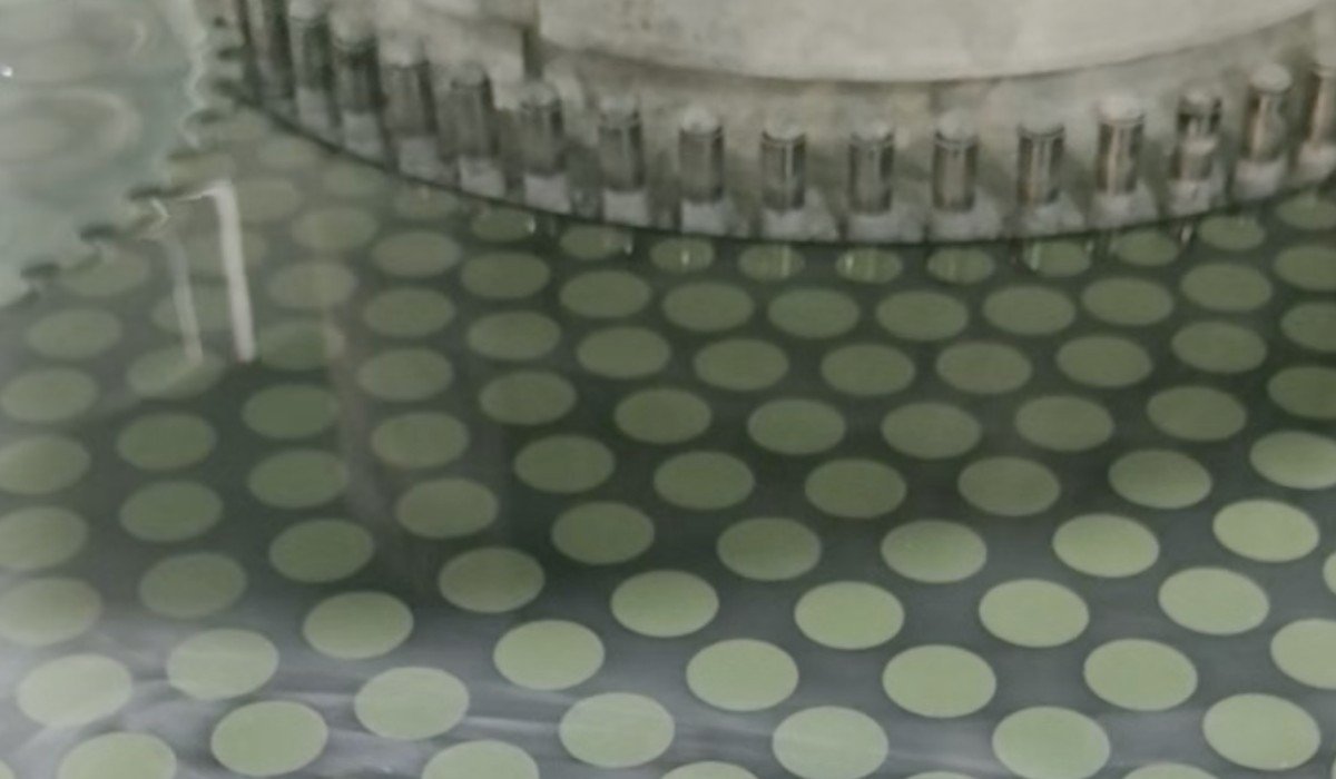
DL-290 or DL-395?
Two sizes of the same double side lapping machine. Choose on the largest part you have to fit and the load that part wants; the rest follows from those two.
| DL-290 | DL-395 | |
|---|---|---|
| Largest workpiece | Ø290 mm | Ø395 mm |
| Planetary carriers | 6 | 5 |
| Maximum working pressure | 400 kg | 700 kg |
| Part thickness | 0.3–30 mm | 0.3–30 mm |
| Take it when | Batches of small and mid flats — one more carrier means more parts per run at a given part size | Large flats, and hard materials that want the load behind them |
Plate diameters, drive ratings, precision figures and the full configuration are on the DL-290 / DL-395 product page, which looks at the same two machines from the wafer and substrate side.
Not a wafer thinning or backgrinding line, and not a 300 mm production tool — that work wants single-wafer grinders, edge trim and cleanroom handling, none of which we build. Not for architectural or decorative glass. And lapping is not polishing: the platform will run a polishing pass with a polishing plate and the matching slurry, but a surface straight off the lap is ground, not polished, and will not read fringes.
Where a double side lapping machine sits in the line
Flat parts take a shorter route than lenses. There is no generating step, because there is no radius to cut, so the blank comes off the saw and goes straight to the lap — and the lap has to deliver both the thickness and the two parallel faces that every station downstream quietly assumes it has.
Curved work goes the other way, through the generating range and then the polishing range. Downstream of the lap, the EP-220C polishes the perimeter of 2D and 2.5D panels, the AOI-20 gauges thickness and sorts, and round elements that need an optical axis carry on to a lens centering machine. How the six stations connect is set out on the fabrication line page.
Send a drawing and a carrier’s worth of parts
Specify a double side lapping machine from a datasheet and you end up comparing plate diameters, which is not what decides the job. Send the part drawing with the diameter, the finished thickness, the TTV and parallelism you have to hold, and the batch size you actually run.
We lap your own blanks, return them, and send the process sheet with the quotation — plate, abrasive, load, cycle time, and the measured five-point map on the parts we ran. The trial run is free; you cover the freight. Quotations are FOB by default, with CNF and DDP on request.
12-month warranty · free trial run on your own blanks
Optics customers include Edmund Optics and Coherent
Related equipment and reading:
- DL-290 / DL-395 wafer lapping and polishing machine — the same pair, full specification, substrate view
- Fine grinding and polishing range — swing machines for curved work
- CNC edge polishing machine EP-220C — perimeter of flat 2D and 2.5D panels
- Lens thickness sorting machine AOI-20 — non-contact gauging and sorting
- Optical lens fabrication line — how the six stations connect
- Full equipment range