
Large Optical Centering Machine EG-185L
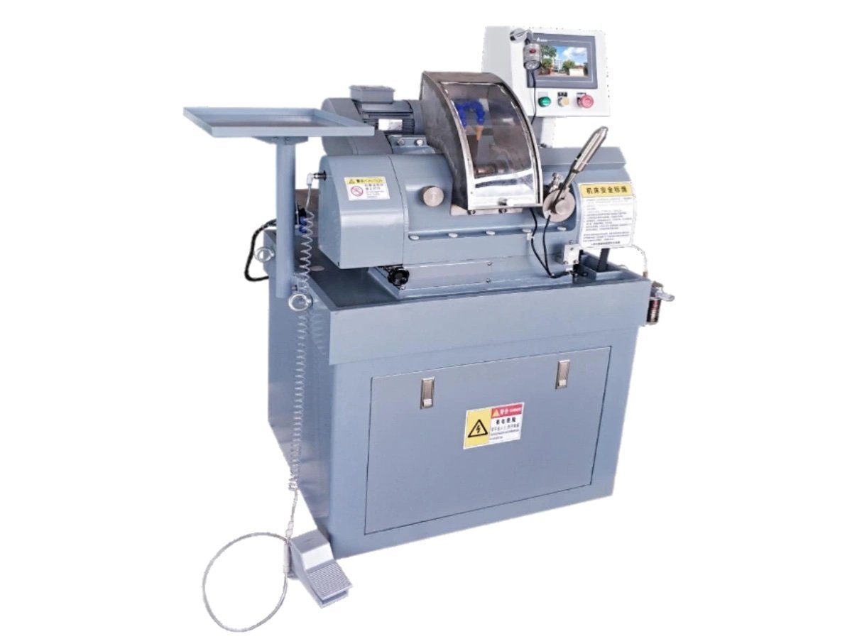
A large optical centering machine for elements up to Ø185 mm. Fixed headstock, servo wheel carriage on X and Y, and a taper micro-adjustment that squares the ground edge without stripping the machine down.
What changes when the element gets big
Centring is the step that makes the optical axis of a finished lens and the outside diameter of that lens the same line. Both faces are already polished when the part arrives; what is still missing is a rim the mount can trust. That job does not change with size — but almost everything about doing it does, which is why a large optical centering machine is a different machine rather than a bigger one.
A Ø180 mm element weighs an order of magnitude more than a Ø30 mm one, has a much longer edge to grind, and is held on bell chucks that are correspondingly larger and heavier. Three consequences follow, and they are what a large optical centering machine has to be built around.
- Mass that defines the axis should not move. Here the headstock is fixed to the bed and the grinding head travels instead, on X and Y guideways
- The edge is long, so angular error shows up as taper. A fraction of a degree between the wheel face and the spindle axis is invisible on a small lens and obvious on a big one
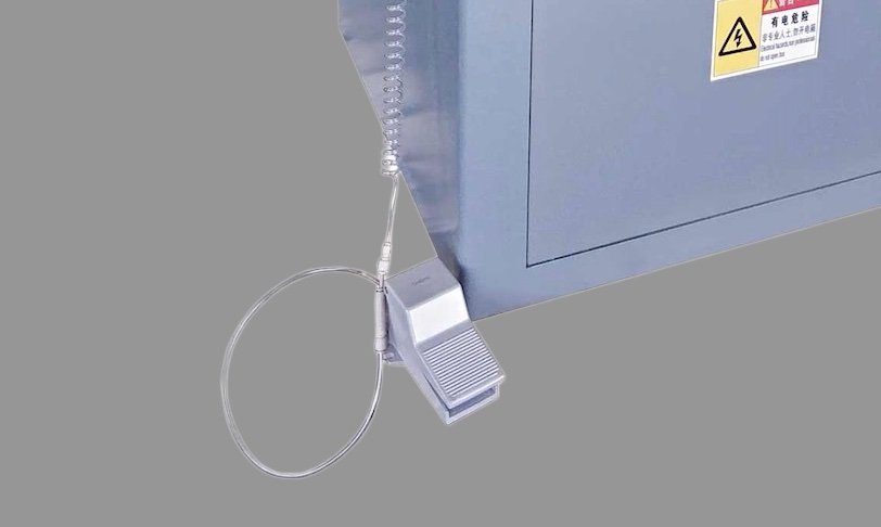
- Parts are loaded by hand. Both of the operator’s hands are on the lens, which is why clamping is on a foot pedal rather than a button
Upstream, elements of this size are generated on the SG-120 large lens curve generator and finished on the polishing range. Downstream is coating and assembly, which we do not build.
Why does a large optical centering machine need a taper adjustment?
Because on a long edge, the two faces of the same lens can come out at two different diameters — and nothing in the cycle tells you it is happening.
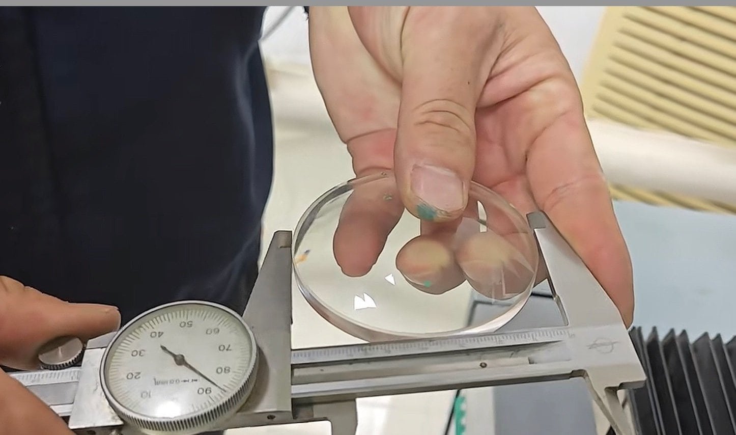
The ground land on a lens edge is a short cylinder. It is only a true cylinder if the working face of the diamond wheel is parallel to the axis the part is spinning about. Let a small angle creep in and the land becomes a cone: the diameter measured at the front face and the diameter measured at the back face are no longer the same number, and the edge no longer seats square in a cell.
The angle comes from ordinary things — a wheel that has worn unevenly, a change of wheel thickness, a carriage that has been apart for service. On small elements nobody notices, because the land is a few millimetres long and the diameter difference stays inside the tolerance anyway. On a Ø150 mm element with a 20 mm land, the same angle produces a difference you can pick up with a micrometer.
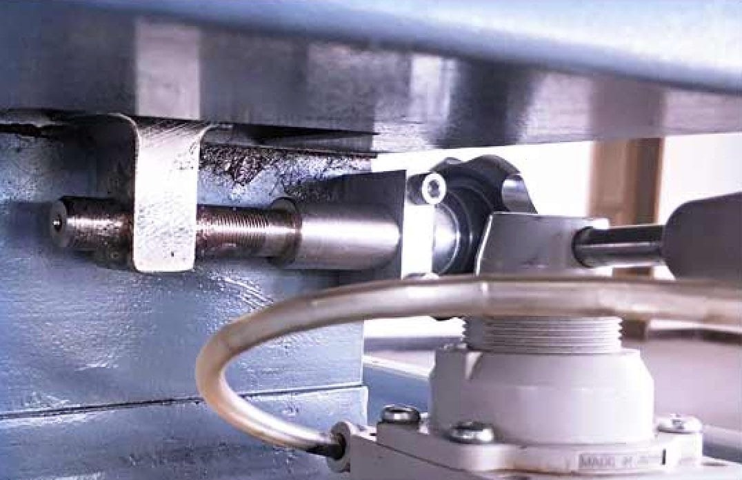
This is why a large optical centering machine of this class carries a dedicated taper micro-adjustment in the mechanical structure of the wheel head. The operator corrects the angle at the machine, during production, on the evidence of the parts coming off it — instead of booking a service visit to re-shim a carriage.
- Adjusted at the machine — the correction is part of normal operation, not a rebuild
- Feeds against 0.001 mm repeatability — there is no point dialling out taper on a slide that cannot come back to the same place
- Holds through a wheel change — a new wheel means a new check, and the check takes minutes
Ask any supplier of a large optical centering machine how taper is corrected on their machine. If the answer involves shims, loosening the head, or a service engineer, that is your answer about how often you will be doing it.
How does the lens end up on its own axis?
The same way it does on every bell-clamp machine, and it is worth being clear that nothing on a large optical centering machine measures the optical axis directly. The lens is trapped between two bell chucks — hollow cones whose rims touch each polished face in a circle — on a holder spindle threaded M20 × 1, right-hand at the fixed end and left-hand at the moving end so that running rotation tightens both halves.
Clamp lightly, spin up, and the part slides on those two rims until the line joining its centres of curvature lies along the spindle axis. That is the only position where the two rim contacts balance. Then the clamp goes to full force and the wheel comes in. The same spindle, run at two speeds:
| Step | Spindle | What is happening |
|---|---|---|
| Alignment | Top of the range | Light clamp; the element migrates on the bell rims until runout collapses |
| Grinding | Low end | Full clamp; the part is locked on its optical axis and the edge is cut |
| Holder drive | 750 W servo, 0–400 rpm | Holding torque at the low end of the band, where a heavy part needs it |
The lens spindle is freely settable from 0 to 400 rpm, and the right pair of speeds is found on trial parts rather than read out of a manual. The geometry of the bell clamp is worked through in more detail on the EG-120L page, which covers the same principle for elements from Ø5 mm.
Centring accuracy on this class of machine is a setting capability, not a per-part measurement. It is established with a centroscope on the first parts of a batch and then repeated; there is no closed-loop gauge reading every element. If your acceptance procedure needs a recorded figure for every piece, say so before you order.
Four structural decisions, and what each one buys you
The architecture of this large optical centering machine is different from the smaller one in the range, and every difference traces back to the weight of the part.
Fixed headstock, travelling wheel head
The holder spindle does not move. The grinding head carries the motion instead, on an X and Y guideway structure driven by servo, ball screw and slide blocks. Whatever vibration the feed system has, it is not being fed into the thing that defines the optical axis.
Oil-immersed slideways
The carriage ways run flooded rather than greased. A continuous film keeps friction even along the stroke, which is what lets a servo hold 0.001 mm repeatability on infeed after a few thousand cycles rather than only when the machine is new.
Rear-mounted wheel motor
The drive motor sits behind the head rather than above or beside it. Mass goes to the back of the structure, the belt run is short, and the vibration that would otherwise print itself onto the long ground land of a large optical centering machine is reduced at the source.
Foot pedal clamping
A Ø180 mm element is a two-hand object. The clamp is actuated by pedal so the operator can hold the lens square to both bells while it closes, and let go only once it is held. There is also an integrated handle for jog and cycle control.

What the digital chamfer aid actually solves
Chamfers are cut at positions the machine knows. The part thickness, however, is whatever the polishing stage left behind — and it varies from element to element inside any real batch. Cut both chamfers at fixed positions and a part on the thick end of the distribution finishes with one chamfer larger than the other, even though the machine did exactly what it was told.
The optional digital chamfering system references the part instead of the machine, so the two chamfers come out the same regardless of where that element sat in the thickness spread. It is the single most common complaint about hand-set chamfering on large elements, and it is the reason the option exists.
| Option | What it does |
|---|---|
| Digital chamfering system | Keeps chamfer size consistent when part thickness varies across a batch; also usable to monitor the centrifugal self-centring step |
| Fixture corrector | Trues the bell chucks in situ, so a worn rim is dressed rather than replaced |
The second function on that first row is worth a sentence of its own. Self-centring is normally something you infer from the finished part; with the digital system fitted, the alignment step on this large optical centering machine can be watched as it happens, which turns setting the centrifugal speed for a new element from guesswork into a five-minute job.

Which materials and part sizes can it handle?
| Item | Capability |
|---|---|
| Operations | Outside-diameter edging concentric to the optical axis, plus chamfering, in one clamping |
| Lens diameter | Ø50 – Ø185 mm |
| Part thickness | Under 60 mm |
| Parts per cycle | 1 — single spindle, single element |
| Materials | Optical glass — this machine is built for glass optics |
| Cycle time | 20 – 2000 s, set per part |
| Wheel | Diamond, Ø160 × 30H7 × 30T, 8–30 mm working thickness |
| Edge geometry control | Multi-stage edging programme plus taper micro-adjustment |
| Loading | Manual, foot-pedal clamping |
If your drawings are dimensioned to the ISO 10110 framework, send one with the enquiry. The centration tolerance and the diameter tolerance on that drawing are what decide whether this large optical centering machine is the right class for the job — more than the material is.
Technical specifications
For elements below Ø50 mm, and for sapphire and other superhard substrates, the machine to look at is the EG-120L.
| Number of spindles | 1 axis |
| Lens diameter range | Ø50 – Ø185 mm (thickness under 60 mm) |
| Working time per part | 20 – 2000 s, set per part |
| Holder spindle thread | M20 × 1 — RH fixed end, LH moving end |
| Holder spindle speed | 0 – 400 rpm, freely settable |
| Holder spindle rotary drive | 750 W servo motor |
| Wheel spindle speed | 3,500 rpm |
| Wheel spindle motor | 750 W |
| Wheel infeed motor | 400 W servo |
| Wheel infeed precision | 0.001 mm |
| Wheel head structure | X / Y guideways, servo with ball screw and slide blocks, oil-immersed ways |
| Diamond wheel | Ø160 × 30H7 × 30T (8 – 30 mm thick) |
| Wheel drive belt | 6-rib poly-V, PJ711 |
| Coolant pump | 90 W |
| Taper adjustment | Mechanical micro-adjustment, standard |
| Fixture corrector | Optional |
| Auxiliary chamfering system | Optional |
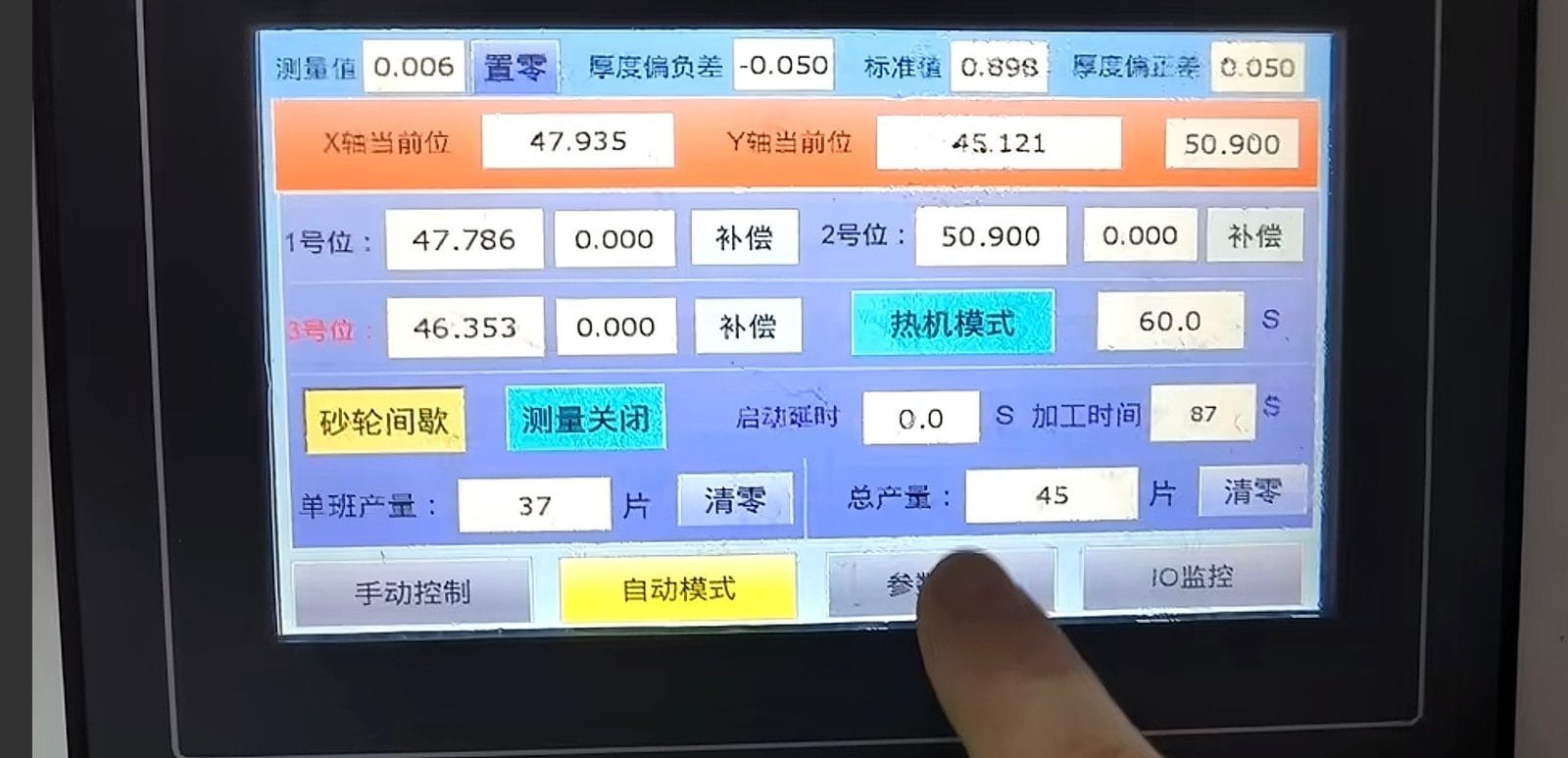
| Control | PLC with 7″ touchscreen |
| Overall dimensions (L × W × H) | 840 × 760 × 1260 mm |
| Total weight | approx. 600 kg |
Principal components
Brands are indicated for reference. Equivalent components of the same or higher grade may be fitted; the stated performance is maintained in all cases.
| Component | Brand / standard |
|---|---|
| PLC and HMI | Premium PLC brand, 7″ colour touchscreen |
| Servo motor and drive | Premium servo brand |
| Wheel spindle bearings | Angular-contact, P4 class, matched set |
| Linear guideways | Premium linear-motion brand |
| Ball screw | Premium ball-screw brand |
| Contactors and electrical | Premium industrial control brand |
Main assemblies and what each one is for
Seven groups make up this large optical centering machine. If something needs attention on the shop floor, this is the vocabulary your operator and our service engineer will share.
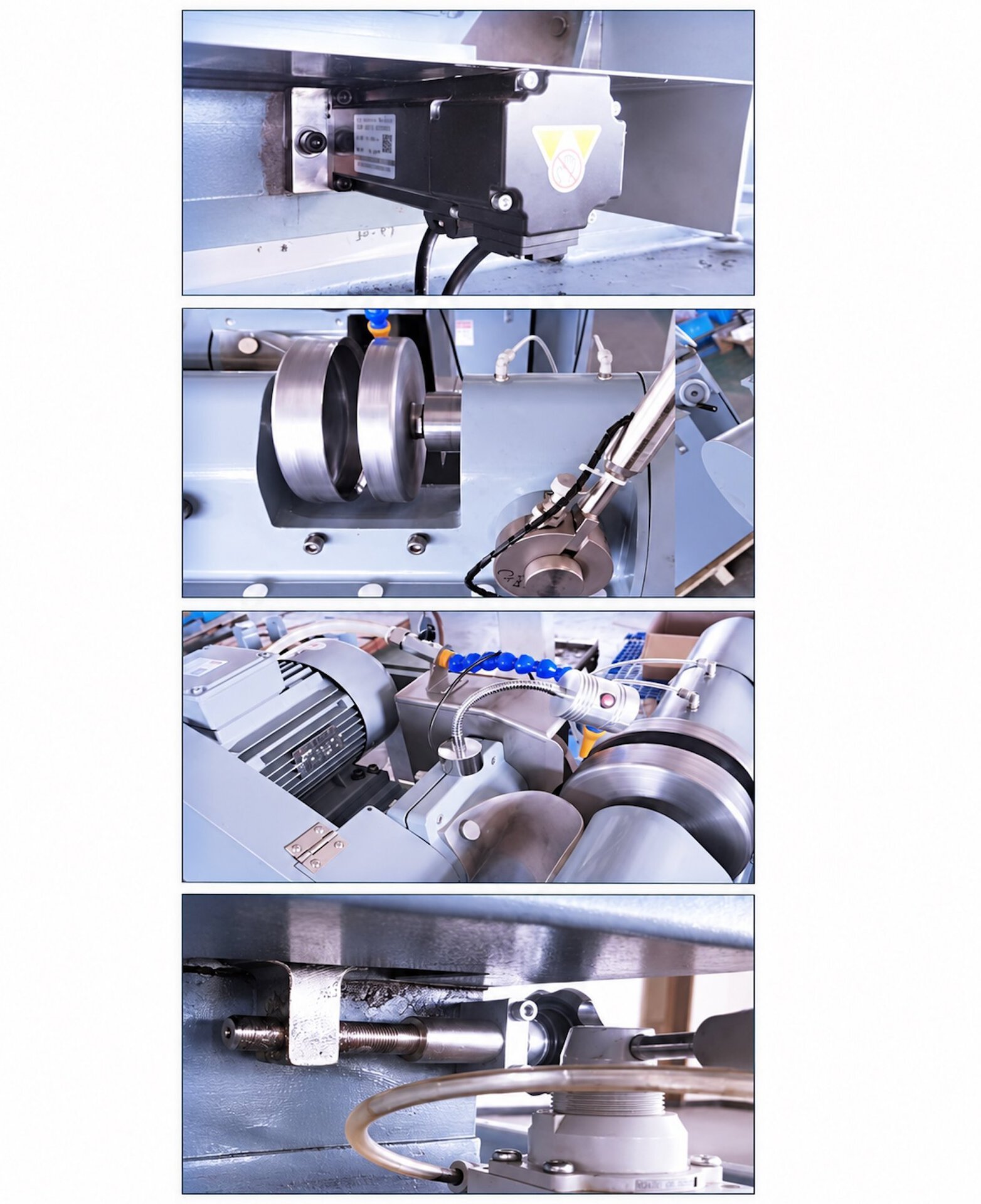
| Assembly | Function |
|---|---|
| Fixed headstock | Bed-mounted holder spindle carrying the bell chucks; runs the alignment and grinding speeds under servo drive |
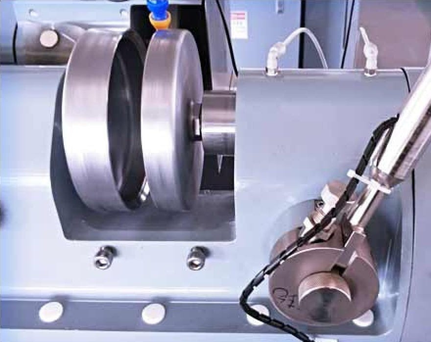
| Bell chuck set | Two-part clamp, M20 × 1 RH and LH, sized to the element diameter and its radii |
| Wheel carriage | X / Y guideway structure on servo, ball screw and slide blocks, running on oil-immersed ways |
| Wheel head | Ø160 diamond wheel at 3,500 rpm on a matched P4 bearing set, motor mounted at the rear |
| Taper adjuster | Mechanical micro-adjustment setting the wheel face parallel to the holder spindle axis |
| Pedal and clamp group | Foot-actuated clamping with the two force levels the alignment sequence needs |
| Control group | PLC, 7″ touchscreen and integrated handle, with the coolant tank and cabinet in the base |
When should you choose a different machine?
Four machines in our range clamp a lens between bells and grind its rim, and all four settle it onto its own optical axis first. What marks out a large optical centering machine is not how it finds the axis — it is the size range it takes, what defines the finished outline, and who puts the part in the chuck.
- Elements below Ø50 mm — use the EG-120L CNC optical centering machine, which starts at Ø1.8 mm, runs twin servo axes and comes with a fully enclosed powered guard
- Sapphire and other superhard substrates — also the EG-120L, which is specified for them and can be ordered with a variable-frequency wheel drive
- Non-round outlines — squares, D-shapes and cover glass are copied from a former on the EG-80 profile edge grinding machine, or on the automatic Auto-EG-80. Both centre the part the same way this machine does; the former is what decides the shape afterwards
- Loading you never touch — the Auto-EG-80 places each lens in the chuck itself, up to Ø80 mm. Above that the part is a two-hand object and loading stays manual, which is why this machine clamps on a pedal
- Polished edges on flat 2D and 2.5D panels — that is peripheral polishing, done on the EP-220C
- Unpolished blanks — there is no optical axis to find yet. Finish both faces first
Not for architectural or decorative glass, and not for ophthalmic Rx laboratories — this is production equipment for precision optical elements, not for spectacle lens edging.
The edging and centring overview compares all of these side by side if you are still working out which stage of the line you are short of.
Utilities, environment and safety
Electrical supply, compressed air, coolant, floor loading and the ambient conditions the machine is to run in are confirmed with us for each order, together with the safety and protective arrangement supplied with it. These figures depend on the voltage and frequency of your site, the material you are running and the destination market, so we do not publish a single set of them here.
Send us the site conditions with your enquiry and we will return the utility and environmental requirements in writing, before the order is placed.
On a large optical centering machine the diamond wheel and the bell chucks are both process items, chosen for the diameter range and the radii you run. They are quoted separately from the machine.
What happens after the machine is installed?
The same terms apply to every machine we ship, wherever in the world it goes.
| Warranty period | 12 months from final acceptance |
| Response during warranty | Response within 8 hours · solution proposed within 24 hours · issue resolved within 48 hours, including procurement, installation and commissioning of parts |
| Outside the warranty | Service and spare parts available for the life of the machine; damage from misuse or abnormal operation is chargeable |
| Certification | CE |
Specifications are subject to change as a result of continuous design improvement. Minor differences may occur at certain parts. For a binding specification, refer to the order confirmation.
See the machine running
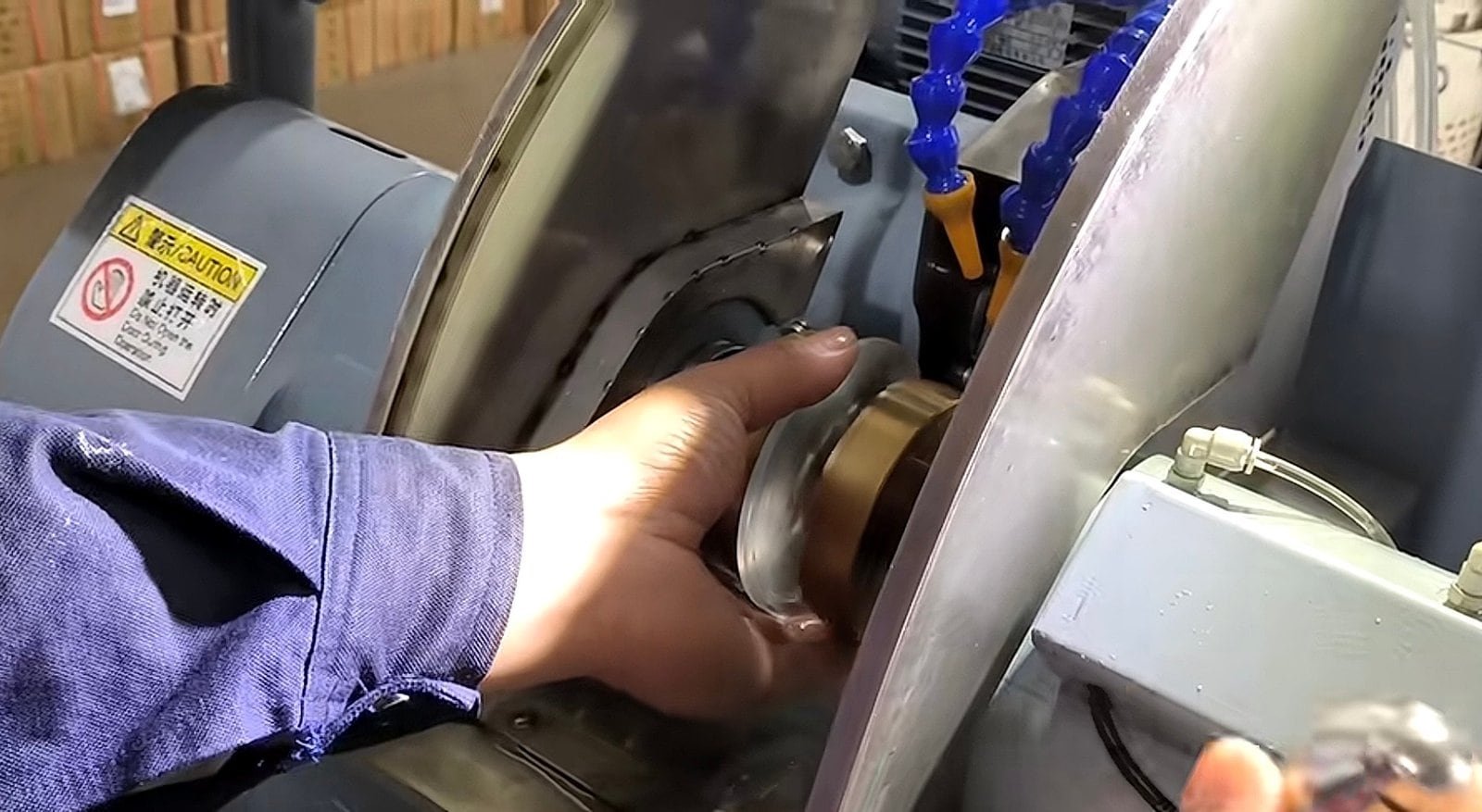
A large optical centering machine loading by pedal, aligning, and taking a long edge in staged passes on an optical glass element.
01 — Pedal loading, self-alignment, edging to diameter
Send one drawing and a few blanks
A large optical centering machine is easy to specify badly from a datasheet, because the number that decides the job is not on the datasheet — it is the bell set. Send us one element drawing with the diameter, both radii, the centre thickness and the centration tolerance you have to hold, together with a few polished parts of your own.
We run them, return them and send the process sheet with the quotation. The trial run itself is free; you cover the freight for the blanks. Quotations are FOB by default, with CNF and DDP available on request.
12-month warranty · free trial run on your own blanks
Optics customers include Edmund Optics and Coherent
Related equipment and reading:
- CNC optical centering machine EG-120L — Ø1.8–120 mm, enclosed, for sapphire and superhard work
- Edging and centring machine range — all four machines compared
- Large lens curve generator SG-120 — the generating stage for the same element sizes
- Optical lens fabrication line — how the six stations connect
- Full equipment range