Getting from a raw germanium ingot to a finished IR lens takes eight distinct manufacturing steps — and every one of them has a way to go wrong. This article covers the full germanium blank to lens process, from incoming material inspection through AR coating and final metrology, with the specific parameters that actually matter at each stage.
What Is the Germanium Blank to Lens Process?
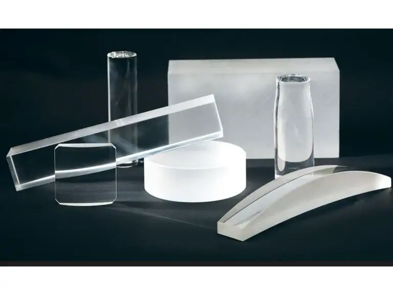
The germanium blank to lens process is the complete sequence of operations that transforms a single-crystal germanium ingot into a finished infrared optical lens — including ingot slicing, blank grinding, double-sided lapping, curve generation, fine polishing, anti-reflection coating, and final inspection. The process is designed to control surface roughness, dimensional tolerances, and optical transmission across the 8–12 μm thermal infrared band.

Germanium Blank to Lens Process: Step-by-Step
Step 1 – Incoming Germanium Ingot
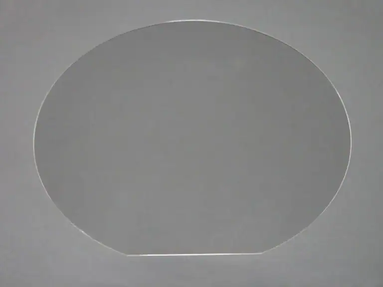
The process starts with single-crystal germanium ingot, and material quality here sets the ceiling for everything that follows. Industrial-grade germanium won’t yield usable IR optics regardless of how well the downstream steps are executed. Specification-grade ingot for optics manufacturing requires purity of 5N+ (≥99.999%), with controlled carrier concentration to achieve the target resistivity — typically 5–40 Ω·cm for standard IR lens applications.
Incoming inspection includes resistivity mapping across the ingot cross-section, dislocation density evaluation by etch-pit counting, and visual check for inclusions or micro-cracks. We reject any ingot showing radial resistivity variation greater than 15% or dislocation density above 500 EPD/cm², because those non-uniformities propagate into optical inhomogeneity that no amount of polishing will fix.
Germanium is sourced primarily from zinc smelting by-product streams. A good reference for material specifications is Umicore’s germanium materials page, which covers purity grades and typical ingot geometries used in optics production.
Step 2 – Ingot Slicing and Blank Cutting
This is where the economics become very concrete. Germanium trades at $1,800–2,400/kg, and every millimeter of kerf is material you paid for that ends up as swarf. In our experience, the slicing stage is where most material loss occurs — not because of breakage, but because of kerf width.
Diamond wire saw cutting is the standard approach for optical-grade blanks. Wire diameter selection directly determines kerf loss: a 0.12 mm wire produces kerf around 0.3–0.4 mm, while a 0.25 mm wire pushes kerf to 0.6–0.8 mm. On a 100 mm ingot sliced into 5 mm blanks, the difference between 0.35 mm kerf and 0.65 mm kerf is roughly 6% more blanks per ingot — at $2,000/kg, that gap adds up fast. For a detailed breakdown of how diamond wire technology reduces kerf loss on germanium, see our germanium lens cutting machine page.
After slicing, blank surfaces show Ra 0.6–1.2 μm, with subsurface damage extending 5–15 μm below the cut surface depending on wire tension and feed rate. The cut surface is not the final reference surface — it’s the starting point for grinding. For process parameters on germanium blank slicing specifically, the germanium lens blank cutting page covers kerf optimization in more depth.
One thing engineers don’t always anticipate: germanium is a p-type semiconductor, and the fine swarf from wire cutting is chemically sticky and difficult to rinse with standard DI water alone. We use a dedicated alkaline cleaning solution (pH 9–10) with ultrasonic agitation to remove the germanium particle film from blank surfaces before grinding. Skip this step and the contamination embeds into the next grinding wheel.
Step 3 – Blank Grinding
Coarse grinding brings the blank thickness to within 0.1–0.2 mm of the target, while reducing the subsurface damage layer left by wire cutting. The goal is to get Ra down from 0.6–1.2 μm to around 0.1–0.3 μm, using a sequence of progressively finer diamond grinding wheels — typically moving from 120-mesh through 400-mesh in two or three passes.
Germanium generates heat quickly during grinding due to its moderate hardness (Mohs ~6) combined with relatively low thermal conductivity (59 W/m·K, about half that of silicon). Coolant temperature control matters here: we hold coolant inlet at 20 ± 2°C. If coolant temperature drifts above 25°C, thermal expansion of the workpiece holder introduces dimensional error that shows up as TTV problems in the next stage. For equipment suited to this operation, see germanium lens grinding equipment.
Step 4 – Double-Sided Lapping
Double-sided lapping is where dimensional control gets serious. The target metric is TTV — Total Thickness Variation — which for a Φ50 mm blank we need to hold to 8–15 μm after lapping. This sets the starting geometry for curve generation; if TTV is worse than 20 μm going in, you’ll fight it all the way through to final polishing.
The lapping process uses a slurry-based abrasive (typically alumina or boron carbide in 3–9 μm particle size) between two opposing lapping plates. Plate flatness, slurry concentration, and carrier rotation speed all need to be dialed in as a system — adjusting one without rebalancing the others usually makes things worse, not better. A well-tuned double-sided lapper on Φ50 mm germanium blanks can hold TTV to 8–10 μm consistently with cycle times of 20–30 minutes per batch.
Step 5 – Curve Generation
Curve generation machines the optical surface radius — spherical or aspheric — into the blank. For spherical surfaces, this is relatively straightforward CNC grinding with a cup wheel, generating the correct radius by setting the wheel tilt angle. Aspheric surfaces require more steps: CNC grinding to approximate form, followed by sub-aperture corrective polishing to bring the aspheric departure within tolerance.
Here’s the practical bottleneck: after aspheric curve generation, every surface needs interferometric verification to confirm the form error before passing to polishing. A well-equipped facility with one interferometer can verify maybe 15–20 aspheric surfaces per shift. If your production mix is predominantly aspheric, this step becomes the rate-limiting constraint for the whole line — not the polishing, not the coating. We’ve seen shops double their grinder capacity while the interferometer queue just grows. Budget the metrology capacity before you buy the generators.
Step 6 – Fine Grinding and Polishing
Fine grinding follows curve generation to remove the surface damage from the generation wheel, typically leaving Ra 10–30 nm before polishing begins. Polishing for IR-grade germanium targets Ra < 1 nm — a requirement driven by scatter losses at 8–12 μm wavelengths where even modest surface roughness contributes to transmission degradation.
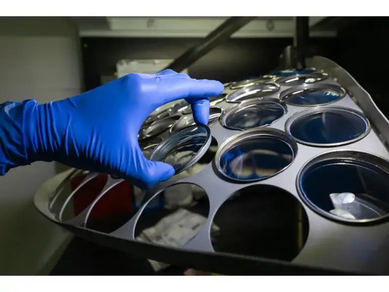
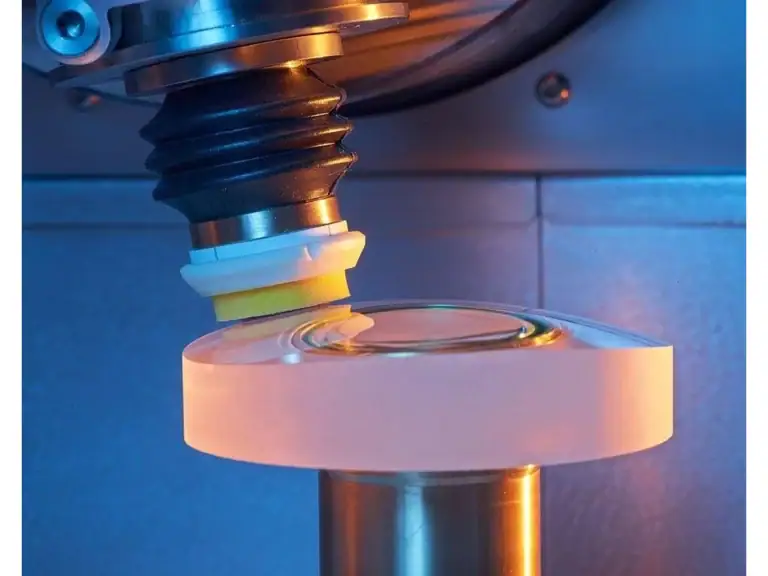
The polishing process uses pitch laps or polyurethane pads with cerium oxide or diamond slurry in the 0.1–0.5 μm range. Germanium polishes relatively cleanly compared to harder IR materials like ZnSe, but it’s sensitive to pH: slightly acidic slurry (pH 5–6) gives better material removal rates, while more neutral conditions reduce the risk of surface oxidation leaving a thin GeO₂ film that affects coating adhesion. Getting to Ra < 1 nm on a germanium lens typically requires 2–4 hours of polishing, depending on blank diameter and form complexity. For polishing machine options used in IR optics production, see germanium optics polishing machine.
Step 7 – AR Coating
A bare germanium surface reflects about 36% of incident 10.6 μm light (refractive index ~4.0 at that wavelength). That’s simply not usable in any system requiring throughput. Anti-reflection coating brings single-surface reflectance from ~36% down to <0.5%, achieving overall lens transmission >99% across the 8–12 μm band.
The standard AR coating architecture for germanium IR lenses is a multi-layer stack — typically YF₃/ZnS or DLC (diamond-like carbon) as the outer hard layer for environmental durability, deposited by thermal evaporation or sputtering at substrate temperatures of 150–250°C. Layer thickness tolerances need to be held to ±2% for the coating to hit its >99% transmission target; broader tolerances shift the reflection minimum out of the 8–12 μm design window.
One known limitation: DLC-coated germanium lenses show adhesion degradation above 60°C humidity cycling if the germanium surface has any residual GeO₂ from the polishing stage. The fix is a brief HF vapor etch (3–5 seconds) immediately before loading into the coating chamber — an easy step to skip, and an easy failure mode to generate.
Step 8 – Final Inspection
Final inspection covers four measurement categories:
Dimensional: Center thickness ±0.05 mm, diameter tolerance h6, radius of curvature ±0.5% from design, surface form error ≤λ/4 at 10.6 μm (confirmed by IR interferometry or contact profilometry).
Optical: Transmission ≥99% across 8–12 μm band, measured by FTIR spectrophotometry on a calibrated bench. Any lens below 98.5% transmission gets routed back to coating review.
Surface quality: Scratch-dig per MIL-PRF-13830 (typically 60-40 for standard IR lenses, 40-20 for imaging applications). Inspection under 100-150W collimated light at multiple angles.
Cleanliness: Particle count on final surface per ISO 14644-1 Class 5 or better, verified before packaging.
Lenses that pass all four categories are packaged individually in nitrogen-purged gel-pak trays. Germanium is sensitive to prolonged humidity exposure — surface haze can develop on uncoated areas within weeks if storage humidity exceeds 70% RH.
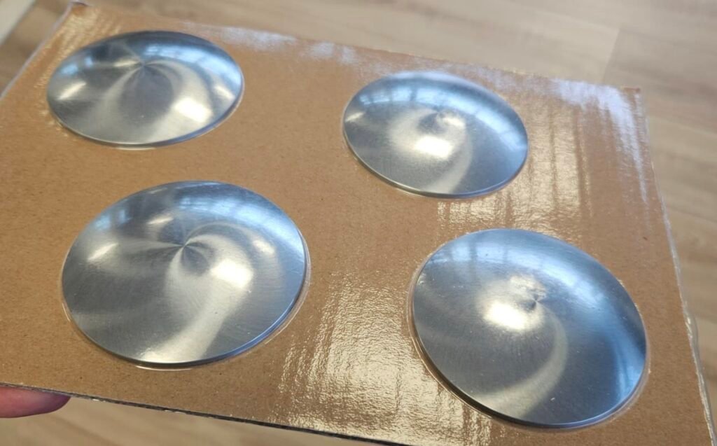
Key Quality Parameters in Germanium Lens Manufacturing
| Process Stage | Control Parameter | Typical Target Value |
|---|---|---|
| Incoming Ingot | Purity | ≥5N (99.999%) |
| Incoming Ingot | Resistivity | 5–40 Ω·cm |
| Wire Saw Slicing | Kerf width | 0.3–0.8 mm (wire-dependent) |
| Wire Saw Slicing | Surface roughness (Ra) | 0.6–1.2 μm |
| Coarse Grinding | Surface roughness (Ra) | 0.1–0.3 μm |
| Double-Sided Lapping | TTV (Φ50 mm blank) | 8–15 μm |
| Fine Grinding | Surface roughness (Ra) | 10–30 nm |
| Polishing | Surface roughness (Ra) | <1 nm |
| AR Coating | 8–12 μm band transmission | >99% |
| Final Inspection | Form error | ≤λ/4 at 10.6 μm |
Why Kerf Loss Matters in Germanium Blank Cutting
Germanium is priced at $1,800–2,400/kg — roughly 10–15× the cost of silicon per kilogram, and germanium blanks are denser, so the cost per unit volume is even more unfavorable. Every millimeter of saw kerf converts material you’ve already purchased into abrasive slurry. On a Φ76 mm ingot being sliced into 3 mm nominal blanks, moving from a 0.65 mm kerf wire to a 0.35 mm kerf wire recovers approximately one additional blank per 25 mm of ingot length. Over a production run of 200 mm ingots, that’s 3–4 additional blanks per ingot at no additional material cost.
The calculation gets more favorable the thinner your target blanks. For 1.5 mm blanks destined for compact thermal cameras, kerf-to-blank-thickness ratio can easily exceed 25% with wide-kerf wire. Switching to fine-diameter wire saw cutting and optimizing wire tension and feed rate is the single highest-ROI process change most germanium optical shops can make. For a detailed kerf loss analysis specific to germanium optical cutting, see germanium lens blank cutting.
Diamond wire saw technology also produces cleaner subsurface damage profiles than ID (inner-diameter) blade sawing, which reduces the grinding stock needed in the next step — a secondary material saving that compounds with the direct kerf reduction.
Equipment Used in the Germanium Blank to Lens Process
Each stage of the germanium blank to lens process requires dedicated equipment matched to germanium’s specific properties:
| Process Stage | Equipment Type | Key Selection Criteria |
|---|---|---|
| Ingot Slicing | Diamond wire saw | Wire diameter range, tension control, coolant filtration for Ge swarf |
| Coarse Grinding | Single/double spindle surface grinder | Diamond wheel bond type, coolant temperature control |
| Double-Sided Lapping | Planetary double-sided lapper | Plate flatness, carrier geometry, slurry delivery uniformity |
| Curve Generation | CNC optical generator | Axis interpolation accuracy, sub-aperture capability for aspheres |
| Polishing | CNC pitch/polyurethane polisher | Load cell feedback, pH-controlled slurry delivery |
| AR Coating | PVD/PECVD vacuum coater | Substrate temperature control, layer thickness monitoring |
| Final Inspection | FTIR, interferometer, scratch-dig station | Calibration traceability, throughput for production volumes |
For a comprehensive overview of the full equipment line for infrared optics production, the infrared optics manufacturing equipment pillar page covers machine selection across all IR materials including germanium, ZnSe, and ZnS.
For technical background on germanium in IR optics applications, the Photonics Media article on germanium optics for infrared applications provides useful context on material properties and transmission windows.
Full-Process Equipment and Process Support
Whether you’re setting up a new germanium optics line or optimizing an existing one, the eight-step process from ingot to finished lens has multiple points where equipment selection and process parameters interact. Getting the slicing and grinding stages dialed in correctly reduces the burden on polishing; getting polishing right makes the coating step more predictable; getting coating right reduces final inspection fallout.
Our equipment is used across all stages of the germanium blank to lens process, from diamond wire saws for blank cutting through polishing machines and grinding systems. If you’re evaluating equipment for a specific step — or planning a complete production line — contact us with your blank geometry, target throughput, and surface specification. We’ll work through the process parameters with you.