APPLICATION NOTE / OPTICAL ENGINEERING

ISO 10110 Drawings: Which Machine Holds Which Tolerance

An optical drawing connects design requirements to manufacturing and inspection. Each callout needs a process owner, a defined datum and a verification method; the drawing alone does not establish machine capability.

That distinction matters when reviewing an ISO 10110 drawing. The series standardizes how optical elements and systems are represented, including their characteristics and tolerances. A drawing may combine optical-surface requirements, centering or tilt, dimensions, material information and edge details. Those requirements belong to different stages of a process. Treating them as one machine specification can create a quotation that looks complete while leaving the actual acceptance method unclear.

Read ISO 10110 callouts by characteristic

Before comparing quotations, list each requirement separately. Preserve the callout and record its datum, evaluation area, measurement method and acceptance limit where specified. Do not infer missing conditions from a machine brochure.

Drawing characteristicBuyer’s questionProcess area to review
Surface form or radiusWhich face, aperture and reference define the form?Curve generating followed by fine grinding, polishing and the specified inspection
Centering and tiltIs the requirement relative to an optical axis, mechanical axis or a named datum?Optical centering or another explicitly defined datum-transfer operation
Center or edge thicknessWhere is thickness measured, and between which references?Generating or lapping process, then a measurement method suited to the part geometry
Outside diameter and edgeAre bevel, chamfer, edge break or contour called out?Profile edging, dedicated centering and edging, or another specified edge operation
Material and internal qualityWhich grade and material condition apply?Incoming inspection and process validation; equipment alone cannot establish material conformity

The table is a workflow aid, not a substitute for the standard. The applicable part of ISO 10110 depends on the characteristic: ISO 10110-1 defines general drawing layout, while ISO 10110-6:2025 addresses centering and tilt tolerances. Verify the edition cited on the drawing.
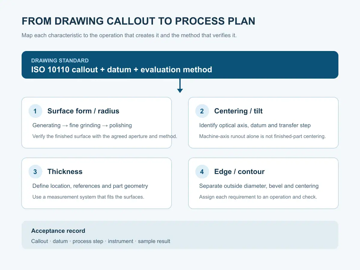
Optical drawing characteristics mapped to generating, finishing, edging and inspection steps
Process map: drawing callouts lead to different operations and inspection checks; it is a workflow guide, not a tolerance conversion chart.

ISO 10110 surface form: generating, finishing and acceptance

For a spherical lens, generating creates the approximate radius and leaves stock for the next operation. Fine grinding removes the generating damage and brings the surface closer to its final figure; polishing then addresses surface quality and figure under the specified process. The amount of stock, material response, tool condition, fixture and measurement reference all affect the result.

The Auto-SG-50 has in-cycle sagitta measurement with automatic compensation, useful process feedback for repeated spherical work. Its specification also lists an 8,000 rpm tool spindle. Neither figure proves that a finished surface meets every form callout on an ISO 10110 drawing. Define how sagitta relates to the required radius and aperture, the finishing allowance, and the final inspection method.

For the optical-generating range, see the optical lens grinding machine range. Ask which operation creates the radius, how much stock remains for finishing, and what measurement confirms the drawing requirement.

Video — Auto-SG-50 automatic grinding cycle

CNC Optical Curve Generator Auto-SG-50 automatic grinding cycle. This clip is an equipment example; it does not define a universal process setting.

Centering and tilt: identify the axis before discussing the machine

Centering requirements are easy to misunderstand because an optical axis and a mechanical axis are not automatically the same reference. The drawing or linked specification must state what is being compared and how the datum is established. A machine that grinds a lens outside diameter can define its mechanical edge accurately while still needing a separate optical-centering step to relate that edge to the optical surfaces.

ISO 10110-6:2025 covers rules for indicating centering and tilt tolerances for optical elements, subassemblies and assemblies. For a buyer, the practical review is to identify the applicable surface or assembly, datum axis, datum point and tolerance indication. If any of these are absent or ambiguous, resolve the drawing question before approving an acceptance plan.

Do not read a machine-axis runout number as the finished optical-centering tolerance. The Auto-EG-80 lists dual-axis runout of ≤0.006 mm. This is a machine specification. A finished lens requirement also depends on how the optical axis is measured, how the part is held, what datum is transferred and how the result is checked. Ask for a demonstration using the same definition that will appear in the acceptance record.

If the drawing requires optical-axis centering, review the CNC optical centering machine separately from the optical lens edging machine range. Record the distinction in the process route so a datum-transfer operation is not omitted.

Thickness: state the location, reference and measurement method

“Thickness” may mean center thickness, edge thickness, flat-part thickness, or a local dimension between specified surfaces. These are not interchangeable. Before quoting, identify the measurement location and reference surfaces, the part orientation, and whether the inspection is contact or non-contact. A thickness tolerance without those conditions can produce different results in two inspection setups.

The AOI-20 provides a non-contact probe specification of ±0.2 µm for flat-part thickness sorting. This is relevant when the drawing calls for that measurement; it is not a universal method for curved-lens center thickness.

The DL-290 lapping platform lists a workpiece thickness range of 0.3–30 mm. That range describes the process envelope, not a finished thickness tolerance. State how stock is removed, how parallelism and thickness are evaluated, and how results are sampled or sorted.

Select the process and inspection method from the part geometry and drawing definition.

Video — AOI-20 non-contact thickness sorting

Lens Thickness Sorting Machine AOI-20 non-contact thickness sorting. This clip is an equipment example; it does not define a universal process setting.

Edge and contour requirements need their own acceptance line

An edge callout can affect assembly, handling and downstream coating. Separate outside diameter from bevel or chamfer, and distinguish a profile requirement from centering relative to an optical axis. If an edge is allowed to remain rough after generating, state which later operation finishes it. If a protective bevel is required, define its width, angle and measurement method rather than treating “edge finish” as a single vague request.

For a profiled lens, the edger may control contour and chamfer; optical-axis centering can require a separate datum-transfer step. The optical lens edging machine range and optical lens fabrication line show the equipment family and process handoff. Do not assume one station removes every error created earlier.

Some drawings use GOST 2.412-81, a standard for drawings and diagrams of optical products. Keep its callouts in their original form and confirm which standard and inspection rule govern acceptance. Unless the drawing package provides a controlled crosswalk, do not assume a symbol or tolerance grade maps directly to ISO 10110; confirm the specific acceptance rule with the customer before quoting conformity.

When one drawing includes several optical elements, make a separate route and acceptance record for each element. A shared machine family does not make the datum, aperture or finishing allowance identical across every part. Keep drawing revision, part identity and inspection result connected so a measurement cannot be assigned to the wrong surface or work order. For mixed lots, identify the applicable element on each inspection record.

Turn the drawing into a machine and inspection plan

Before requesting a final quotation, send the complete drawing and a short characteristic list. For each requirement, record:

  1. The exact callout and the drawing revision.
  2. The feature and datum it applies to.
  3. The operation expected to create or correct the feature.
  4. The inspection method, instrument and evaluation area.
  5. The sample quantity and the pass/fail rule for the trial.

Then ask the equipment supplier to separate machine specifications from the finished-part result the trial must prove. Record the incoming dimensions, setup, process sequence, finishing stock and output measurements against the same drawing revision and datum.

An ISO 10110 drawing is actionable when every callout has a process owner and inspection method. This makes quotations comparable and separates machine specifications from finished-part acceptance.

Frequently asked questions

Does ISO 10110 specify which machine must produce a tolerance?

No. It standardizes the representation of optical characteristics and tolerances. The process route and machine capability must be evaluated against the part geometry, datum and inspection method.

Does machine-axis runout prove finished optical centering?

No. Runout is a machine specification. Finished centering also depends on the optical-axis measurement, workholding, datum transfer and final inspection.

Can a thickness tolerance be quoted without a measurement location?

Not reliably. Identify the surfaces, location, orientation and reference used for the measurement before setting acceptance criteria.

Send one drawing for an application review

Share the drawing revision, material, incoming blank size, expected quantity and acceptance method. The team can map the callouts to generating, finishing, edging and inspection, then define checks for a free sample cutting trial.

Scroll to Top