
Pitch Polishing: Why Optical Shops Still Use It
Pitch polishing is useful when a conforming lap and controlled surface contact are required during finishing. Pitch is viscoelastic: it responds to load and temperature over time rather than behaving like a rigid metal tool. That conformity can help maintain contact on a curved surface, but it also means lap condition, support, polishing motion and slurry must be controlled. Pitch polishing is a process choice, not an automatic route to a better surface.
The decision is usually between a pitch lap and a polyurethane pad for a defined material, curve and acceptance requirement. Compare the surface correction needed, the tool’s contact behavior, conditioning effort, batch repeatability and downstream measurement. A pad may suit repeatable production where its compliance and texture match the part; pitch may suit applications where the lap is formed or conditioned to the surface and the process requires a conformal tool. Neither is universally faster or more accurate.
What pitch polishing changes
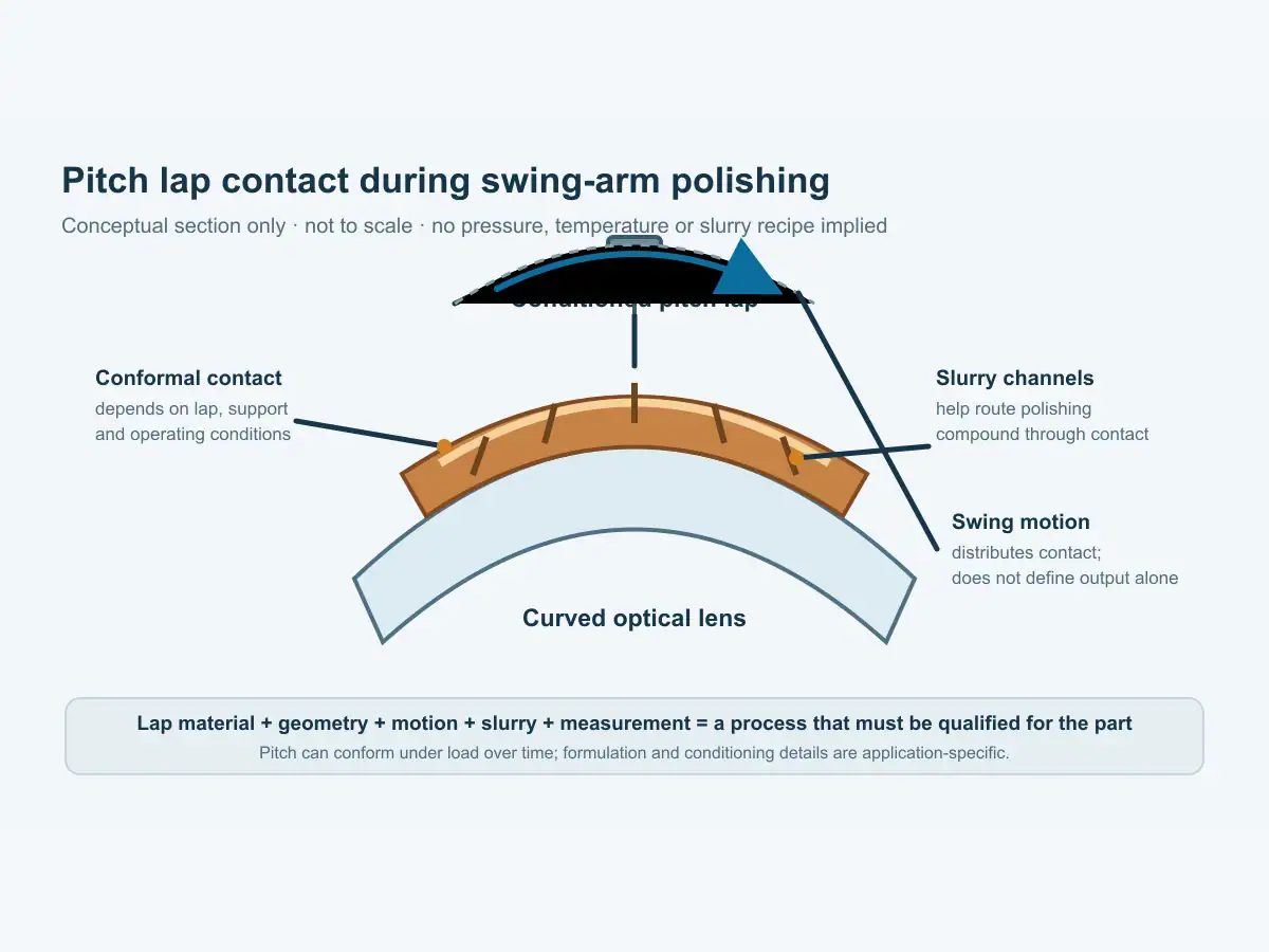
A pitch lap presents a working surface against the optical lens with polishing compound between them. Under controlled motion and load, the interface removes material. The lap’s geometry and surface pattern affect how it contacts the lens and how slurry moves through the interface. As the pitch slowly deforms, it can accommodate small shape differences, but that behavior changes with formulation, temperature, time under load and support.
This is why pitch polishing requires attention to tool condition. Shops may press or condition a lap so its surface conforms to the intended part and preserves channels for slurry flow. The exact method is process-specific. Pitch formulation, temperature and conditioning values should come from a qualified shop procedure or a controlled trial for the tool and part; they should not be generalized across polishing setups.
Compare polyurethane pads and pitch polishing
Polyurethane polishing pads provide a different interface. Their manufactured texture and compliance can support controlled polishing when the pad, slurry and process parameters are suitable for the lens. They may be easier to standardize across repeat runs than a hand-conditioned pitch lap, depending on the part and shop’s process controls. Pad selection still needs to account for curvature, surface quality, slurry delivery and the behavior of the specific material.
Research comparing pitch and polymer laps shows that the outcome depends on the combination of material, abrasive and lap; a result from one set of test conditions is not a universal ranking. For production selection, compare both routes on representative parts with the same incoming surface condition and acceptance method. Measure the characteristic that matters—such as surface figure, roughness or scratch-dig—rather than relying on the visual appearance of the tool.
Use a pad when a repeatable consumable fits the contact geometry. Pitch polishing may suit a curve or finishing objective that benefits from a conformal tool. If part geometry changes, include the time and skill needed to prepare or verify each tool.
The role of swing motion
A swing-arm polishing machine moves the work spindle through an arc relative to the lap or polishing plate. The motion distributes contact over the working region. The result depends on the swing geometry, spindle rotation, tool shape, part support, pressure and slurry. A machine’s motion range does not, by itself, define a finished figure or surface quality.
The Vimfun FP-4U is an upper-swing configuration for concave lenses. Its documented range is R1–R20, maximum Ø30, with spindle speed 450–3000 rpm. The FP-4L uses a lower swing for convex lenses and lists ±R1.5–R50. These specifications identify the intended geometry and machine envelope; they do not imply that every material or surface grade can be polished without a validated tool and process.
The optical lens polishing machine range is the main equipment overview. Review the FP-4U concave lens polishing machine for the upper-swing route and the FP-4L convex lens polishing machine for the lower-swing route. Choose the swing direction from the surface geometry, then confirm radius, part size, workholding and tool access against the drawing.
Pitch polishing is not lens blocking
Blocking attaches and supports a lens for an operation. Pitch polishing describes the lap material and the finishing interface. Blocking may be part of a polishing setup, but it does not define the polishing tool or prove that the part is finished. Keep the support method, lap geometry and polishing process as separate items in the process plan.
The lens blocking and deblocking guide addresses workholding and release. Polishing still requires a suitable lap, slurry and motion for the drawing; correct blocking alone does not establish surface acceptance.
Set up a controlled comparison
A useful comparison of pitch polishing and pads begins with representative lenses from the same material and upstream process. Record geometry, incoming condition, blocking method, tool identity, slurry and setup. Use the same measurement procedure before and after polishing; changing several factors at once obscures the cause of a result. For pitch polishing, repeat the check across an actual representative batch so the prepared lap is assessed beyond the first lens. Log any resurfacing or conditioning between parts.
For a pitch trial, document lap preparation and conditioning steps without treating them as universal values. Check contact across the intended region, confirm slurry reaches the interface and inspect the lap for damage or uneven support. For a pad trial, record the pad type and condition, dressing or break-in method if applicable, and the slurry pairing. Follow the supplier’s process instructions for both tools.
Measure the lens using the drawing’s reference and acceptance method. Surface figure, roughness and scratch-dig are different characteristics. One cannot substitute for another. If the next operation is coating, define what inspection happens before coating and which surface condition is required at the handoff.
Repeat the comparison on enough parts to reveal whether the outcome is stable across the intended batch. Record the tool condition before and after the run, and keep a retained sample when the customer’s quality plan permits it. A single clear-looking lens is useful for setup, but it does not establish repeatability or replace the specified measurement record.
Separate setup results from production acceptance. The trial should use the same drawing revision, measurement reference and handling practice intended for the released process.
What the machine video shows
The FP-4U clip shows a four-spindle upper-swing machine with polishing and optional automatic loading, inspection and flipping. It is an equipment example; the video does not specify pitch formulation, lap conditioning or process settings. Ask for a trial with the actual lens geometry when those details determine the selection.
Decide from the part and the process record
Pitch polishing is worth retaining when its conformal contact and conditioning method solve a defined finishing need. A polyurethane pad can be preferable when its contact behavior and repeatability fit the surface and production schedule. Confirm the choice with a controlled comparison; do not infer the result from tool material alone.
Before approving a route, ask who conditions the lap, how the tool is inspected, how the workpiece is supported, what measurement demonstrates the output and how often the tool must be refreshed. Those questions expose the labor and control requirements behind a polishing method. They also help buyers compare an established pitch process with a pad-based setup on the same basis.
Send a lens drawing for process review
Share the material, concave or convex surface, radius, diameter, incoming finish, target surface requirements and production quantity. Include the current blocking method and inspection data if available. Vimfun can review the suitable swing configuration and define measurements for free sample cutting or polishing before the machine choice is treated as final.
Frequently asked questions
Why is pitch used for optical polishing?
Pitch is a viscoelastic lap material that can conform to the surface under controlled load and temperature. Its suitability depends on the part and process.
Is pitch polishing the same as lens blocking?
No. Pitch describes a polishing interface; blocking describes how a part is mounted or held.
Can a pad replace pitch on every surface?
No universal substitution applies. Compare compliance, surface geometry, process stability and measured output on representative parts.
Sources checked
- Vimfun, Optical Lens Polishing Machine range.
- Vimfun, Concave Lens Polishing Machine FP-4U.
- Vimfun, Convex Lens Polishing Machine FP-4L.
- Applied Optics, Polishing study using Teflon and pitch laps to produce flat and supersmooth surfaces.
- FP-4U video, Vimfun YouTube.