
Lens Center Thickness: Contact vs Non-Contact Measurement
Lens center thickness is the axial distance between the two optical surface vertices. It is not edge thickness, total height in an arbitrary fixture or one surface’s sagitta. The method must locate both vertices and establish the lens axis or a defined reference; otherwise a repeatable number can still describe the wrong dimension.
In production, lens center thickness is commonly checked with a contact gauge, coordinate setup or qualified optical probe. Select the method from part geometry, material, coating, required uncertainty, cycle time and support conditions.
Define the dimension before choosing an instrument
For an axial measurement, define both surfaces and the axis between their vertices. On a plano-convex lens, these are the plane and curved-surface vertex; for meniscus or biconvex parts, orientation also matters. An off-axis reading is not the specified value unless a procedure converts it.
State nominal value, tolerance, measurement location, datum or centering method and relevant conditions. Include temperature control when it matters. If the drawing only says “thickness,” confirm whether it means lens center thickness, edge, local or assembled thickness before programming inspection.
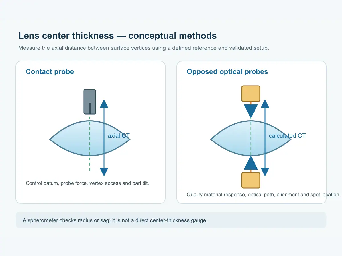
Contact measurement: direct, but setup-sensitive
A dial indicator, height gauge or coordinate measuring machine can provide a contact measurement. Support the lens on a defined datum and probe the opposite surface at its vertex, or use a validated reconstruction. If the fixture tips or shifts the part, the measured distance changes.
Contact methods are direct for suitable materials and tolerances, but probe force, tip radius, contamination and alignment matter. Protect delicate or coated surfaces and support the part without distortion. A height-gauge value is only meaningful with its reference, probing point and orientation defined.
If a steep surface prevents probing the vertex, an accessible off-axis point does not preserve the same lens center thickness value. State how the vertex is located or the reading corrected, and retain the calculation, calibration and probe setup.
Non-contact measurement: avoid touch, control the optics
Optical approaches locate surfaces without contact and may use confocal, interferometric or other ranging principles. A two-sided arrangement can measure each surface from a controlled reference and calculate axial separation. For curved parts, alignment and spot location remain critical; sensor resolution does not remove these geometric requirements.
Non-contact systems avoid probe force and support automation, but response can depend on reflectivity, transparency, slope, coating and optical path. Qualify the instrument on the actual material and geometry. Confirm whether it measures both surfaces, calculates from a model or reports another feature such as surface form.
Published methods describe astigmatic-autofocus and chromatic-confocal approaches to non-contact lens thickness. They establish that such methods exist, not that a given shop instrument is qualified for every glass type or tolerance.
| Method | Useful when | Validate before use |
|---|---|---|
| Dial or digital gauge | A defined contact point and accessible geometry are available | Datum, force, tip access and operator repeatability |
| Coordinate measurement | Both surfaces can be sampled and the vertices reconstructed | Point strategy, alignment, stylus access and calculation |
| Optical probe pair | Contact is undesirable or automated surface positioning is needed | Material response, spot location, axis alignment and calibration |
| Spherometer | Surface radius or sag is the process question | Support geometry and radius method; it is not a direct thickness reading |
A qualified lens center thickness setup must return the drawing’s axial distance. A fast sensor can remain biased if it measures another surface point or misses a steep lens vertex.
A spherometer is not a center-thickness gauge by itself
A ring-type spherometer checks curvature through sag over a known support geometry. It can verify a radius, but does not measure both vertices. Deriving lens center thickness from its reading requires other dimensions, references and a validated calculation. Keep radius checks separate from direct thickness inspection.
A spherometer may support a radius check after generating, but that check must remain distinct from direct center-thickness measurement.
Repeatability is a process result, not just a display resolution
Repeatability depends on calibration, seating, orientation, probe or optical spot, temperature, operator and data handling. Display resolution does not prove repeatability on production lenses. Study representative parts with the intended fixture, operators and sequence.
For contact checks, verify datum return and probe force. For optical checks, verify centering and sensor locations. Record whether the result is a reading, average or calculated vertex separation, and use a suitable calibrated reference.
When readings disagree, compare reference, point and orientation before changing the process. Tilt, support, an off-axis probe or different calculation conventions can explain a mismatch; repeating without controlling them can hide its source.
Separate instrument repeatability from reproducibility across shifts. Have more than one operator repeat the same defined procedure, remove and reload the part, and include parts spanning the expected range. Review the spread and any systematic offset against a calibrated reference. If the production fixture changes, repeat the study; a result qualified on a laboratory stand does not automatically transfer to an automated nest. Use this evidence to decide whether a single check, sampling or 100% classification is justified for the lens center thickness requirement.
Where automated sorting fits
Measurement and sorting serve related but distinct purposes. A measurement station estimates a defined feature; a sorter assigns parts to bins under a specified rule. Before sorting, establish the measurement method, band limits, reject logic and traceability record. The bin labels should not imply a tolerance that the inspection system has not demonstrated.
The AOI-20 page describes non-contact thickness sorting for flat optical parts: probe accuracy ±0.2 µm, throughput ≥2000 pcs/h, and OK 6 + NG 2 channels. These values apply to flat-part sorting, not curved-lens lens center thickness. The video shows flat parts gauged and routed into thickness bands.
The LI-20 page describes non-contact curved-surface form measurement, with repeat accuracy ±0.0015 mm and cycle time 2 s. Surface form is distinct from lens center thickness; these figures apply to the stated form measurement. See the LI-20 page for its scope.
Set the measurement cycle around the production question
For each part family, decide between 100% sorting, periodic checks, first-piece approval or lab verification. Include presentation, cleaning, measurement, classification and reject handling in the production cycle; a sensor cycle alone is not line takt.
Sampling may suit the process risk. For 100% sorting, define invalid-reading handling and record part ID, value, channel and recheck where traceability is needed. Assess uncertainty, repeatability and throughput separately.
Lens center thickness can change during generating, fine grinding and polishing. The optical lens grinding machine range covers upstream geometry operations. Agree which step brings thickness into tolerance, what stock remains and where final acceptance occurs; a machine envelope does not prove finished capability.
A practical measurement plan
Before buying or programming a system, document:
- The exact surfaces and axial reference defining the dimension.
- Lens material, geometry, diameter, coating and allowed contact condition.
- Required range, tolerance, uncertainty and repeatability study.
- Fixture, orientation, measurement points and vertex calculation.
- Production rate, sampling rule, reject bands and traceability needs.
Compare contact and optical methods on the same representative parts, including samples near tolerance limits. Confirm with manufacturing and quality teams how the result maps to the drawing before setting sorter channels or release limits.
Frequently asked questions
How should center thickness be measured on a curved lens?
The method must locate both surface vertices along the defined lens axis, or use a validated calculation that reconstructs their axial separation. Record the fixture, orientation, measurement points and calculation.
Can a spherometer directly measure center thickness?
No. A ring-type spherometer checks surface curvature from sag over a known support geometry. It does not measure both vertices; any thickness calculation needs additional references and validation.
Does the AOI-20 measure curved-lens center thickness?
The cited AOI-20 specification covers non-contact thickness sorting of flat optical parts. It does not establish curved-lens center-thickness capability.
Which is better for production, contact or non-contact measurement?
Neither is universally preferable. Compare material response, geometry, coating, probe access, uncertainty, repeatability and cycle time on representative parts using the drawing’s acceptance method.
Send the drawing and a measurement sample
Share the lens drawing, material, center-thickness tolerance, surface geometry, coating status, production quantity and current inspection method. The team can help define the measurement question and upstream route, then agree checks for a free sample cutting trial. The sample report should identify the measurement method and reference so the lens center thickness result can be reproduced.
Sources
- Vimfun, AOI-20 lens thickness sorting machine.
- Vimfun, LI-20 automatic curved-lens surface-form measurement.
- Vimfun, Optical lens grinding machine range.
- Optics Express, Method of non-contact measurement for lens thickness using astigmatic auto-focus probe.
- Applied Optics, Thickness measurement of plane-parallel plates and lenses using chromatic confocal sensor.
- Vimfun, AOI-20 non-contact thickness sorting video.