
Lens Centering Machine
A lens centering machine does not grind a diameter to size. It finds the line joining a finished lens’s two centres of curvature, then grinds the rim true to that line. Ø1.8–185 mm, optical glass through sapphire.
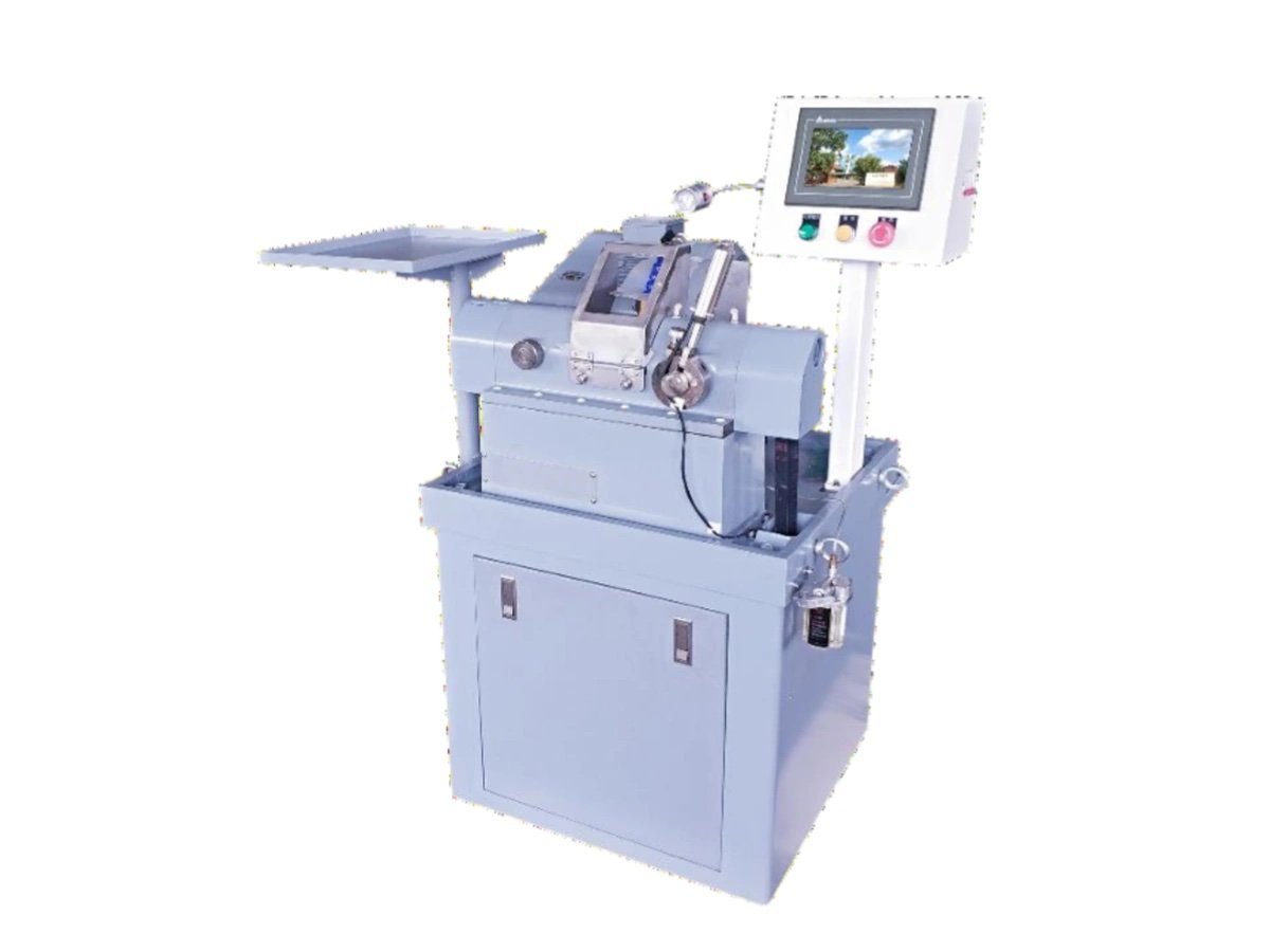
What centring actually decides
A polished lens has two optical surfaces, each with a centre of curvature. The line through those two centres is the optical axis — the axis the element actually images about. Nothing in sawing, generating or polishing references it. The blank was round before any of that started, and it stayed round about whatever the saw happened to give it.
So when the lens goes into a cell, two axes meet: the axis of the bore, and the optical axis of the glass. If they are not the same line, the beam leaves the assembly pointing somewhere other than where the design says. You can build that error out with shims and adjustment rings, or you can remove it once, at the rim, before the lens ever reaches assembly. That second option is what a lens centering machine is for.
Generating and polishing decide what shape the lens is. A lens centering machine decides where it is — relative to the tube it gets screwed into.
How does a lens centering machine find the axis?
It does not measure it. It lets the lens find the axis by itself.
The element is trapped between two bell chucks — short hollow cones whose rims touch each polished face in a circle rather than at a point — on a single horizontal spindle. Clamp lightly, spin it up, and the part will not stay where you put it. Each rim pushes on a spherical surface, and the only position where those two pushes balance is the one where the line joining the two centres of curvature lies along the spindle axis. Anywhere else there is a sideways component, and the lens slides on the rims until that component disappears.
Then the clamp goes to full force, the spindle drops to the low end of its range, and the diamond wheel comes in. The rim that gets ground is concentric with the optical axis because the optical axis is now the axis of rotation. Two actions, one spindle:
- Settle — light clamp, top of the speed range, the part free to migrate on the rims until runout collapses
- Cut — full clamp, low speed, outside diameter and both chamfers in the same setting
The bell set is the tooling that makes this work, and it is chosen for the diameter and the radii you run — not supplied as one universal pair. Tell us the range of elements and we specify the set with the quotation.
Because the part is located by its own polished faces, a lens centering machine does not care much what the glass is. What decides the job is the radii, the clear aperture and the centration tolerance on the drawing.
How is centring accuracy set and checked?
This is the question that decides whether one lens centering machine quotation is comparable with another, and it is the one most datasheets answer with a number and nothing else. A number on its own is not a specification. Ask three things instead.
| Ask | What a straight answer looks like |
|---|---|
| With what? | A centroscope — the operator watches the reflected image of the surface centre while the part turns, and adjusts until it stops describing a circle |
| Under what conditions? | Named bell set, stated clamping force, a specific radius and diameter. Change any of those and the figure changes |
| How often? | Established on the first parts of a batch, then repeated by the machine. There is no closed-loop gauge recording every element |
That last row is the one to get in writing before an order, not after. A setting capability and a per-piece record are different commitments, and a supplier who lets you assume the second while delivering the first has built a dispute into the acceptance procedure. We would rather be explicit: what this class of machine gives you is a setting, established on a centroscope and then repeated.
If your process genuinely needs a recorded figure for every element, say so with the enquiry. That is a different class of equipment and we will tell you so rather than quote for it.
Arc-second claims circulate freely in this category. Before comparing two of them, check that both refer to the same thing — setting capability on a centroscope, at a stated bell size and radius — because usually they do not.
Drawings dimensioned to the ISO 10110 framework already carry centration as its own tolerance, which makes this conversation short. Send one with the enquiry.
Four machines, three things that separate them
All four machines in this part of the range clamp between bells and settle the element on its own optical axis before the wheel comes in. Centring is not what distinguishes a lens centering machine from a profile edger.
Size
Ø1.8–120 mm and Ø50–185 mm on the two dedicated centring machines; up to Ø80 mm on the two profile edgers. The overlap in the middle is real, and the tie-breaker is usually one of the next two.
What defines the outline
Round parts take their diameter from the wheel. Squares, D-shapes and cover glass need a copy former, which only the profile edgers carry. A lens centering machine finishes the part round.
Who loads it
One machine in the four takes the element to the chuck itself. The other three are hand-loaded — which is the right trade on short runs and mixed batches, and the wrong one at volume.
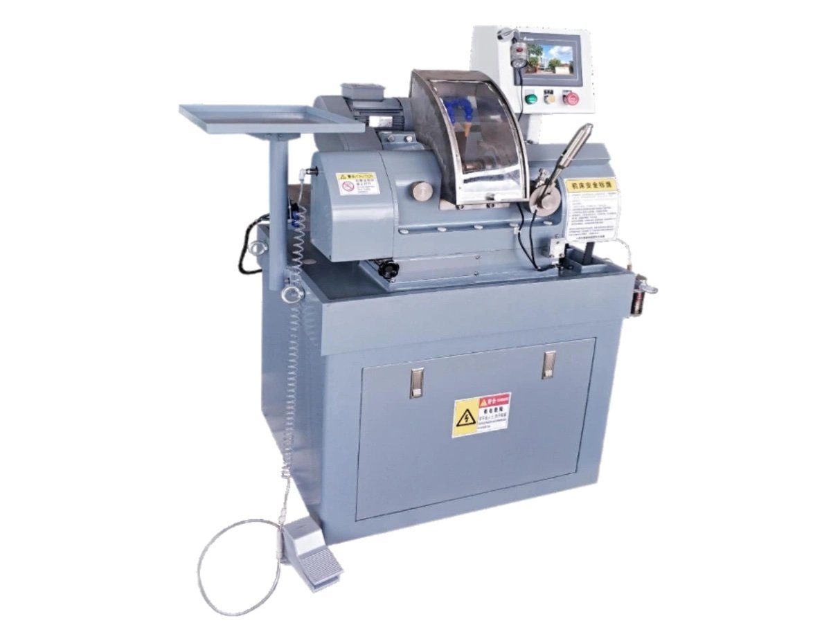
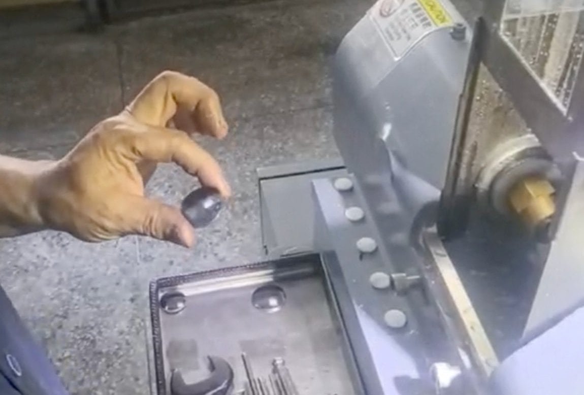
Which machine for which part?
| Machine | Take it when | Range |
|---|---|---|
| EG-120L | Round parts, small to mid; sapphire and other superhard substrates; you want the cut enclosed | Ø1.8–120 mm |
| EG-185L | Round parts above Ø120 mm; long edges where taper has to be dialled out at the machine | Ø50–185 mm |
| EG-80 | Non-round outlines copied from a former, hand-loaded, mixed batches | Ø5–80 mm |
| Auto-EG-80 | The same work as EG-80 at volume, with the element placed in the chuck automatically | Ø5–80 mm |
Two of these have a further difference worth knowing before you compare quotations: the EG-185L carries a taper micro-adjustment as standard, and can be ordered with a digital chamfering system that keeps both chamfers equal when part thickness varies across a batch. The EG-120L answers the same problem differently, with twin servo axes and a constant depth of cut set as a number.
Not for architectural or decorative glass, and not for ophthalmic Rx laboratories. This is production equipment for precision optical elements. Edge polishing on flat 2D and 2.5D panels is a different operation again, done on the EP-220C.
Where centring sits in the line
Centring is late. Both faces have to be finished before there is an optical axis to find, which means every hour already spent on the element is at risk on this machine — and it is also the last chance to correct what the earlier stations left.
Upstream is the generating range and the polishing range; the edging and centring overview compares this station against the rest of stage 4. Downstream is coating and assembly, which we do not build. How the six stations connect is set out on the fabrication line page.
Materials are no constraint in themselves — optical glass, fused silica, crystal quartz, sapphire and technical ceramics all centre on the same principle. What changes with the harder substrates is the wheel specification and the feed a lens centering machine can hold, not the method.
Send one drawing and a few polished parts
A lens centering machine is easy to specify badly from a datasheet, because the item that decides the job is not on the datasheet — it is the bell set. Send one element drawing with the diameter, both radii, the centre thickness and the centration tolerance you have to hold, together with a few of your own polished parts.
We run them, return them, and send the process sheet with the quotation — including how the centring was set and what it was checked on. The trial run is free; you cover the freight. Quotations are FOB by default, with CNF and DDP on request.
12-month warranty · free trial run on your own blanks
Optics customers include Edmund Optics and Coherent
Related equipment and reading:
- CNC optical centering machine EG-120L — Ø1.8–120 mm, enclosed, sapphire and superhard
- Large optical centering machine EG-185L — Ø50–185 mm, taper micro-adjustment
- Edging and centring range — all four machines compared
- Optical lens fabrication line — how the six stations connect
- Full equipment range