Lapping Plate Flatness: Conditioning Rings and Wear
A batch can leave the lapper with an uneven thickness distribution even though the average stock removal matches the recipe. Increasing the cycle may remove more material without correcting the underlying form. Lapping plate flatness is one cause to investigate, alongside loading, carriers, pressure distribution and measurement.
The useful maintenance question is not simply whether the plate looks worn. It is whether the measured plate condition remains within the process window that produces accepted parts. Establish a repeatable plate map, relate it to identified batches and use the machine-specific conditioning method.
01 — Separate plate shape from part specifications
Plate flatness describes the working surface of the tool. Part flatness describes one finished surface, while total thickness variation describes the difference between maximum and minimum thickness over a defined area. These are related through the process, but they are not interchangeable measurements.
A part can have curved surfaces that remain approximately parallel, or flatter surfaces that do not produce the required thickness relationship. Measuring only a center thickness will miss both distinctions.
For lapping plate flatness control, record the plate map and the part results separately. Define the measurement span and reference for each. A local reading across a short track cannot automatically establish the condition of the complete plate.
Use the double-side lapping process guide to connect tooling condition with the complete route rather than attributing every TTV problem to a single variable.
02 — Read lapping plate flatness before correcting wear
A broad concave or convex tendency requires a different investigation from local waviness, a damaged area or a contaminated measuring contact. Describe the pattern and its repeatability before changing conditioning settings.
| Observed pattern | Checks before correction | Useful record |
|---|---|---|
| Broad concavity or convexity | Measurement reference, thermal state and wear distribution | Repeated profiles at defined positions |
| Local waviness or lobes | Tooling motion, loading pattern and local damage | Angular and radial map |
| Sudden local reading change | Debris, burrs and measurement contact | Cleaned repeat reading |
| Drift during production | Load, slurry condition, temperature and conditioning history | Plate and batch results over time |
Do not use an apparent flatness change to explain a batch result until the measurement itself is repeatable. A dirty contact or a different bridge orientation can produce a misleading trend.
Lapping plate flatness belongs in a time record. A single acceptable reading after maintenance says little about how the surface changes during a normal production interval.
03 — Understand what conditioning changes
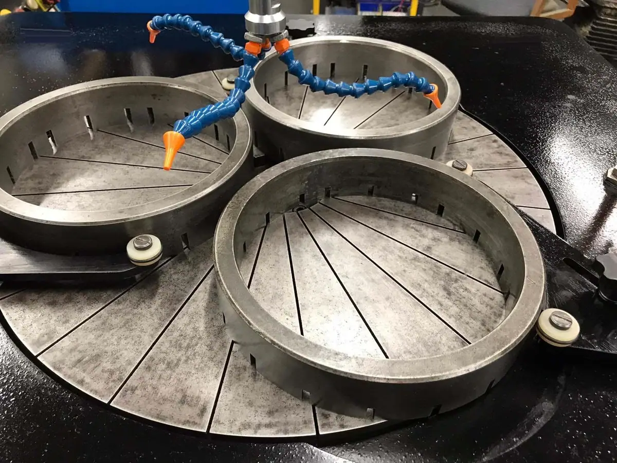
Conditioning redistributes wear or removes high regions using the tooling and motions designed for the machine. Ring location, speed relationships, contact and abrasive condition can influence the wear pattern.
On an open-face ring-lapping machine, changing the radial position of the conditioning ring can alter where wear occurs. However, the direction and magnitude of correction must follow the machine’s documented geometry. Do not transfer a simple instruction from that machine to a double-side planetary system without confirmation.
A double-side machine has additional relationships among upper and lower plates, carriers, gears and workpieces. Correcting one plate or one operating variable may not address the full thickness-distribution problem.
For lapping plate flatness, use a measured correction loop: inspect, apply the approved limited correction, reinspect and confirm with representative parts. An unmeasured long conditioning run can overshoot and create a new problem.
04 — Measure using a defined reference
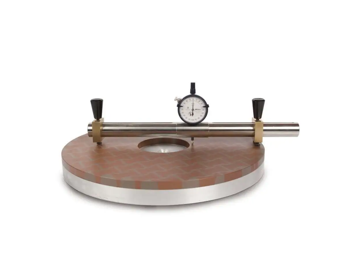
A straightedge can reveal a broad condition, but its contact and resolution limit what it proves. A bridge and indicator require a known reference, consistent span and clean contact points. Instrument resolution alone does not define measurement accuracy.
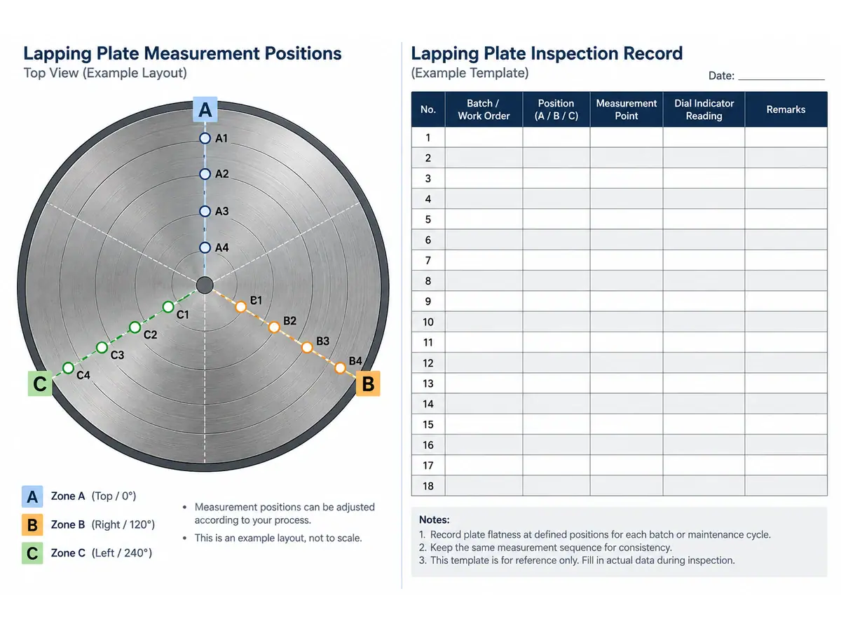
Measure with the machine in the safe condition required by its maintenance procedure. Identify the plate, radial positions, angular locations and thermal condition. Record whether the reading is taken directly on the working land and how grooves are handled.
The NIST guidance on control of a measurement process is relevant here: the measurement system itself needs stable, checked behavior if trends are to support decisions.
For lapping plate flatness records, retain both the readings and the measurement layout. A number marked “flatness” without a span or location cannot be compared reliably with the next shift’s result.
05 — Include loading, carriers and pressure
Part distribution affects contact and wear. An unevenly filled carrier, mixed incoming thicknesses or a changed product diameter can alter the process even when the programmed time remains unchanged.
Check carrier condition and its relationship to the workpiece. A carrier that is damaged or unsuitable for the part can create a problem that conditioning alone cannot solve. Keep part loading and tooling inspection in the batch setup record.
Pressure must be interpreted using the machine’s defined quantity and loaded area. A value displayed as a load is not automatically contact pressure. Avoid describing a kilogram load rating as if it were a uniform pressure acting on every component.
The DL-series lapping and polishing product page provides the equipment context. Use the selected model’s confirmed documentation for settings, rather than combining specifications from different plate sizes or configurations.
06 — Set a conditioning trigger from process evidence
A fixed calendar interval can be convenient, but the wear rate depends on the work being processed. Changes in material, batch loading, abrasive or stock removal may require a different interval.
Establish an initial inspection and conditioning plan through trials. Then compare plate measurements, part results and the amount of work completed. The objective is to intervene before the qualified process window is lost, not to maximize the time between every maintenance action.
Lapping plate flatness should have a documented acceptance criterion and response. State who can authorize a correction, what measurements are required afterward and when a representative batch must be rechecked.
Avoid hiding repeated corrections inside an unchanged recipe. If the plate requires more frequent intervention, investigate the reason: wear distribution, consumable condition, loading or a mechanical issue may have changed.
07 — Link the plate map to the batch map
Identify part positions or carrier groups during a trial. Measure thickness at the agreed locations on released, cleaned parts. Where relevant, measure surface form separately from thickness variation.
Compare the batch pattern with the plate record, but do not assume a one-to-one transfer without evidence. Motion, pressure, part stiffness and carrier behavior can change how a tool condition appears in the finished component.
A lapping plate flatness improvement is useful when it leads to repeatable accepted parts. If the plate map improves while TTV does not, continue the investigation into loading, metrology and the rest of the process rather than repeating the same correction indefinitely.
Retain failed-batch data. It helps distinguish a gradual wear trend from a sudden event such as contamination or carrier damage.
08 — Release maintenance with a complete record
After correction, document the plate condition, tooling used, settings, elapsed correction time and verification result. Include any change to the production recipe. Mark the first qualified batch after maintenance so later performance can be traced to that intervention.
For a supplier review, send the machine model, plate condition map, carrier details, loading pattern and part measurements. Photographs help locate visible damage, but they do not replace the measured reference needed for correction.
Discuss lapping process requirements using the actual material and finished drawing. Lapping plate flatness is a controlled input to the production process; maintaining it works best when tool inspection and part acceptance use the same traceable history.