APPLICATION NOTE / ASPHERIC LENS GRINDING

Aspheric Lens Grinding: Where Spherical Tooling Stops

A machine can have CNC control and still be designed to generate spheres and planes. The controller may manage feed stages, automatic loading or tool compensation without providing the path capability required for an aspheric surface. Aspheric lens grinding must be matched to the actual geometry, motion and measurement system.

Vimfun’s equipment range discussed here covers spherical, plane and cylindrical processing through specific machine configurations. It is not presented as a proven aspheric production platform. This guide explains the difference so a buyer can separate suitable upstream work from a job that requires another class of equipment or a specialist supplier.

01 — Start with the surface equation and drawing

An asphere departs from a simple spherical profile. A common rotationally symmetric description uses a base curvature, conic constant and additional polynomial terms, but the drawing may use another agreed representation. The exact convention, units, aperture and coordinate reference must travel with the data.

Do not describe the job only as a diameter and nominal radius. Those values can define a useful envelope while omitting the departure that makes the surface aspheric. A machine supplier cannot establish suitability from that shortened description.

For aspheric lens grinding, identify the required surface, center and edge thickness, clear aperture and permitted form error. If the component has two optical surfaces, specify their relationship as well. A correct single surface does not automatically produce a correct lens.
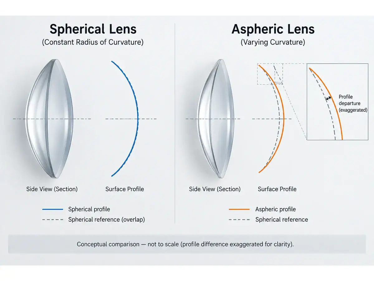
Conceptual comparison of spherical and aspheric lens profiles
Conceptual profile comparison with exaggerated differences; not to scale.

02 — CNC does not mean every surface is programmable

A spherical generating process can use a defined wheel geometry and angle to establish a nominal radius. Controlled feed then removes material toward that geometry. Automation can improve repeatability and handling without changing the family of shapes generated by the mechanism.

Vimfun’s CNC optical curve generator describes spherical and plane surfaces, staged feed and related handling functions. Those features should not be reinterpreted as a demonstrated aspheric tool-path capability.

Quoted featureWhat it may provideWhat still needs proof for an asphere
CNC feed stagesControlled approach and removal sequenceCoordinated surface-generating motion
Automatic loadingRepeatable part transferSuitable holding and reference accuracy
Sagitta measurementA defined height-related process checkFull aspheric form evaluation
Wheel compensationCorrection for a specified tooling conditionCompensation valid over the complete surface

Ask what axes are coordinated, what surface data the control accepts and how the resulting form is measured. The label on the controller is not sufficient evidence.

03 — Tool paths and contact in aspheric lens grinding

Aspheric lens grinding can use controlled tool motion to remove material according to the required profile. Tool shape, contact area, wheel condition and the machine’s kinematics determine how commanded motion becomes a physical surface.

A nominal path alone is not a finished process. Tool wear, alignment, compliance and thermal behavior can produce errors that require measurement and correction. The grinding strategy must also leave an appropriate condition for the later finishing route.

Avoid treating a smaller tool as a universal solution. It can improve local access while changing removal behavior and the spatial character of errors. The supplier must demonstrate a process appropriate to the material, aperture and slope range.

The broad optical lens grinding comparison remains useful for spherical or plane blank preparation. It should not be used to infer an aspheric capability that the selected machine has not demonstrated.
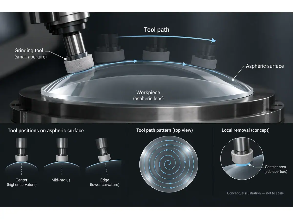
Conceptual tool positions along an aspheric workpiece
Aspheric tool-path concept; not evidence of a specific Vimfun machine capability.

04 — Plan grinding and corrective finishing as a pair

The purpose of grinding is not merely to approach the nominal shape quickly. It must leave sufficient stock for the qualified finishing process while controlling damage and form error. Excess stock may increase finishing time; insufficient stock may make correction impossible.

In aspheric lens grinding, the finishing team needs the measured departure map and the reference used to create it. A polishing process that improves roughness without preserving or correcting the required shape can leave a clear but unacceptable component.

Separate removal of grinding damage from correction of form. They interact through the stock budget, but they are not identical tasks. Define what each stage must achieve and how the handoff is accepted.

Before ordering equipment, identify whether the supplier provides the complete grinding and finishing process, one station only or just tooling. An unassigned correction step can become the largest gap in an otherwise detailed quotation.

05 — Choose metrology before committing the process

A profile instrument can examine a trace, but the trace direction, probe geometry and alignment affect what it establishes. One passing meridian may not establish the condition across the full aperture. Use a sampling and evaluation plan appropriate to the surface and tolerance.

Interferometric testing can require a suitable null arrangement or another method capable of handling the departure. ZYGO’s explanation of computer-generated holograms describes how a designed test wavefront can support measurement of complex surfaces. The optic and test setup must be matched and aligned correctly.

For aspheric lens grinding, agree which terms may be removed during data fitting. An apparently improved residual can result from changing the evaluation rather than improving the physical part. Preserve the raw data and the fitting convention.

Also distinguish surface-form error from transmitted wavefront error. Material, the second surface and alignment can affect the latter. The acceptance requirement should state which result is needed.
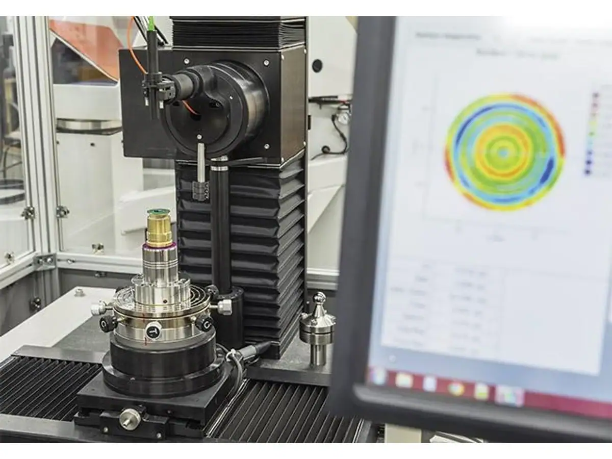
Optical metrology setup with a surface map on screen
Optical metrology setup example. The image alone does not establish suitability for a particular asphere or a valid measurement result.

06 — Cylindrical processing is another distinct capability

A cylindrical surface is not simply a rotational asphere with a different program. Its geometry and processing arrangement differ from a surface that is rotationally symmetric about an optical axis.

The CG-140 cylindrical grinding page describes that specific equipment role. Use it for a cylindrical application review, not as evidence that the machine can generate an arbitrary aspheric or freeform surface.

This distinction matters when comparing quotations. “Curved lens” is too broad a description to determine whether a spherical generator, cylindrical machine or aspheric platform is required. Send the actual drawing and surface definition before discussing capacity.

Aspheric lens grinding should remain a separate capability question even when the same factory also needs spherical and cylindrical parts. A shared material does not make the machines interchangeable.

07 — When outsourcing is the better route

A low-volume program with changing designs may not justify a dedicated machine, specialized tooling and metrology. The required process development and measurement expertise can exceed the cost suggested by the grinding machine alone.

Compare the complete route: equipment, fixtures, software, test optics, operator development, finishing and inspection. Include the risk of rejected development parts and delayed qualification. A quotation that omits these items is not a like-for-like comparison with a specialist’s finished-part price.

For aspheric lens grinding, outsourcing can be appropriate when the geometry is outside the demonstrated internal capability or the expected volume is too uncertain. Keep a clear incoming acceptance plan so outsourced parts are measured against the same drawing and data conventions.

This is a process-boundary decision. It does not prevent the buyer from preparing compatible blanks or producing other spherical and plane components in-house.

08 — Make the capability boundary explicit in the enquiry

Send the surface definition, material, aperture, thickness requirements, slope or access concerns and proposed measurement method. Identify the annual volume and expected design changes. Ask the supplier to separate demonstrated capability from work requiring development.

Vimfun can review the relevant spherical, plane, cylindrical and blank-preparation operations within its documented range. An aspheric production requirement needs an explicit capability assessment; it should not be accepted on the basis of a generic CNC description.

Use the application contact page to share the drawing and define the appropriate equipment scope. A useful aspheric lens grinding discussion ends with a supported process decision, including referral or outsourcing when the requirement falls outside that scope.

Scroll to Top