
Lapping Process: Reaching Thickness and Parallelism
Flat optical parts often need two things at once: a controlled thickness and faces that stay parallel. The lapping process is one route for correcting a flat part after cutting or generating. It uses an abrasive interface between a workpiece and a lap plate to remove material. The outcome depends on how the part is supported, how the plate and carrier move, what abrasive system is used, and how the result is measured.
For flat optical glass, windows and substrates, the route links incoming stock, lapping, polishing and inspection. Equipment selection depends on the drawing and batch.
What the lapping process changes on a flat optic
Lapping removes material while bringing a surface toward a flatter condition. In double-sided work, parts sit in carriers between upper and lower plates, so both faces are processed in the same cycle. It does not automatically deliver a polished optical finish; a later polishing step may be required by the surface specification.
The lapping process is therefore best specified with more than a target thickness. Buyers should also state the part material, starting thickness, diameter or outline, required flatness, parallelism, thickness variation, surface condition and final measurement method. If any values depend on polishing or another finishing operation, keep those acceptance requirements distinct from the lapping target.
How the lapping process spreads contact
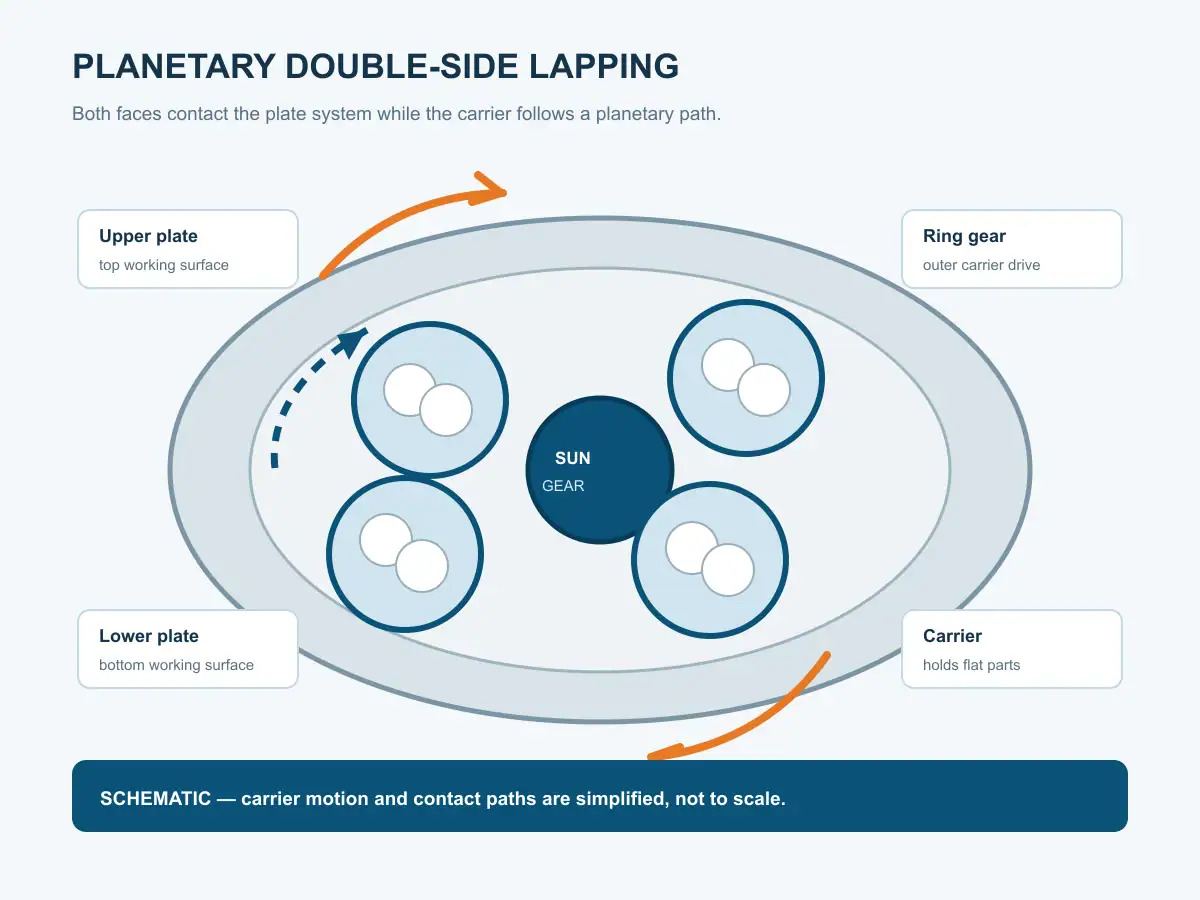
In a planetary double-side setup, carriers hold the parts in cutouts. A sun gear near the center and a ring gear around the perimeter drive the carriers as the plates rotate. Each carrier turns while traveling around the plate, so parts do not follow a single circular track. This motion distributes contact over the working surfaces and helps the batch see a more averaged path.
The figure shows the mechanism conceptually, not a prescribed recipe. Actual motion depends on machine design and rotation directions; plate flatness, carrier condition, abrasive and starting geometry also affect the result.
The lapping process depends on moving surfaces as well as load. Plate flatness, carrier wear and uneven loading can change thickness distribution, so review them with the machine, consumables and measurement plan.
Fixed abrasive or slurry: define the process route
An abrasive may be carried in a slurry or presented through a fixed-abrasive surface, depending on the job and machine setup. The choice changes how abrasive reaches the interface, how the plate is conditioned, how debris is managed and how the process is monitored. Do not assume one method suits every material or finish requirement.
For a new job, record the abrasive type and condition, delivery method, plate material and conditioning approach. Confirm how the machine is cleaned between materials and how spent slurry or process debris is handled. A supplier may recommend a starting route, but the lapping process should be validated on representative parts rather than selected from a generic recipe.
Concentration, particle size, speed and pressure interact. Starting settings depend on material, stock removal and downstream polishing, so establish them through a representative trial rather than treating one value as universal.
Control thickness without confusing it with parallelism
Thickness is a dimension between two surfaces. Parallelism describes how those faces relate to each other; flatness describes the form of an individual face. A part may meet a thickness target at a measurement point while still failing a face-form or parallelism requirement elsewhere. A buyer should name the metric and the instrument used to judge it.
During the lapping process, the initial stock and part orientation affect how much material needs to be removed from each face. A batch with uneven incoming thickness can consume extra cycle time and create a wider output spread. Sorting incoming parts into sensible groups, using consistent carrier loading and measuring a sample at defined locations can make the result easier to diagnose.
Total thickness variation (TTV) is a useful batch metric when the drawing or customer specification defines how it is calculated. It should not replace explicit flatness and parallelism requirements. Agree whether the measurement is point-to-point, map-based or based on another named method, and specify the support condition for thin parts. Without that information, two inspection reports may describe different quantities using the same label.
Pressure, plate speed and carrier loading
Pressure changes the abrasive contact and removal behaviour. Plate speeds and rotation directions influence the relative path. Carrier loading affects how much part area is available and whether the batch is balanced. These variables are related: increasing one does not guarantee faster or better processing if the abrasive interface, plate condition or part support is unsuitable.
The DL-290 / DL-395 family provides a concrete equipment example. DL-290 lists a maximum workpiece diameter of Ø290, 6 star wheels, a 0.3–30 mm part thickness range and 400 kg plate pressure. DL-395 lists up to Ø395, 5 star wheels and 700 kg plate pressure. These are machine specifications, not guaranteed finished flatness, parallelism, removal rate or yield.
Compare configurations against part size, carrier loading, material and batch size. Loading and cleaning can affect throughput, so ask how the carrier supports the part and how incoming and outgoing measurements will be recorded.
Loading and what the video shows
Operators load parts into planetary carriers, position the carriers on the lower plate, and close the machine according to its operating procedure. The illustrated video shows the DL-290/395 loading flat parts into carriers before double-side lapping. It is useful for understanding the handling sequence; it does not establish a process setting or quality result.
Include carrier inspection, orientation, plate conditioning, cleaning, measurement and changeover when estimating labor and throughput; a cycle time alone is incomplete.
How to judge output from the lapping process
Measure representative parts using the agreed reference, instrument, support and evaluation locations. Keep incoming measurements and sample positions so removal and output variation can be traced to the starting condition.
The lapping process output should be checked for the characteristics that matter downstream: thickness, flatness, parallelism, surface condition and remaining stock for polishing. If the next step is polishing, confirm that it can remove the residual surface damage without exceeding the final thickness limit. A trial is useful when the same part moves through the intended route and the final report records each handoff.
Review plate condition separately from part quality. Plate maintenance belongs in the machine process-control plan; the workpiece route must control thickness and parallelism against the drawing.
Lapping and polishing are different steps
Lapping is a material-removal operation that helps establish geometry and thickness. Polishing uses a different interface and process objective to improve surface finish and, where specified, figure. The same machine platform may support more than one mode on some configurations, but the consumables, conditioning and acceptance criteria remain process-specific.
Do not describe the lapping process as polishing simply because both operations can use a plate and an abrasive. A lapped surface meets an optical polish requirement only when the measurement and specification support that conclusion. A separate comparison article can be linked here after it is published and verified.
For equipment context, the DL-290/395 wafer lapping and polishing machine lists its documented envelope. Application and inspection requirements still come from the part drawing.
A practical sample-trial checklist
Before a trial, provide the material grade, part drawing, incoming dimensions, required thickness and parallelism, flatness or surface requirements, batch size, and the next operation. Ask the supplier to record the carrier arrangement, abrasive route, plate condition, process settings and measurement method. Identify which values are machine limits and which are trial results.
During the trial, inspect a representative group and record incoming and outgoing measurements. If results vary, compare carrier position, orientation, plate condition and loading balance before changing one process factor at a time.
After the run, confirm polishing stock, cleaning and inspection against the drawing. A useful trial produces an agreed measurement record, not just a completed machine cycle.
Select equipment when its part envelope, abrasive route, plate motion, loading plan and inspection method fit the drawing. Use a representative trial to establish conditions for the actual material and batch.
Send a drawing and sample parts
Share a drawing, material, starting dimensions and production quantity. The application team can review whether double-side lapping fits the flatness, thickness and parallelism requirements, then define the measurements for a free sample cutting trial. Compare the trial report with the same drawing revision and acceptance method that will be used in production.
Frequently asked questions
Does lapping control thickness and parallelism equally?
They are separate characteristics. The process and inspection plan should define how each is measured and controlled.
Is slurry lapping the only lapping route?
No. Fixed-abrasive and slurry routes are different process choices; select and qualify the route for the plate, machine and required result.
Does carrier loading determine the final result by itself?
No. Loading interacts with plate condition, abrasive delivery, motion and process time. Confirm results by measurement.