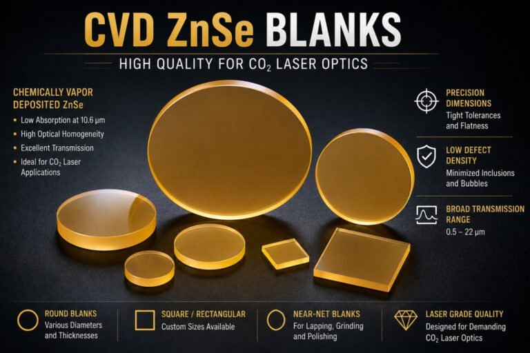
A ZnS optics cutting machine is precision slicing equipment configured specifically for zinc sulfide — a brittle infrared optical material that fractures readily under conventional cutting forces and loses surface integrity when exposed to thermal shock during processing. Selecting the right machine and process parameters determines whether ZnS blanks arrive at polishing with the geometry, surface condition, and structural integrity that downstream processing requires.
What Is a ZnS Optics Cutting Machine?
A ZnS optics cutting machine separates zinc sulfide optical blanks from CVD-grown boules or slabs into individual substrate forms — windows, lens blanks, dome preforms — at the dimensions and surface quality required for subsequent grinding and polishing.
ZnS does not respond well to the cutting approaches used for metals or even for harder crystalline materials. Its polycrystalline CVD grain structure, low fracture toughness, and moderate thermal sensitivity mean that cutting forces, heat generation, and vibration must all be controlled within tighter margins than most general-purpose slicing equipment provides. A machine that cuts germanium accurately may still chip ZnS edges or introduce subsurface damage that only appears during polishing, when the damaged layer is exposed.
The two equipment types used for ZnS optics cutting are diamond wire saws and inner diameter (ID) saws. Each has a different force profile, kerf geometry, and throughput characteristic. The choice between them depends on blank size, required surface quality, production volume, and the downstream tolerances the polishing process must achieve.
ZnS Material Properties That Determine Cutting Equipment Requirements
Zinc sulfide used for infrared optics is produced by chemical vapor deposition (CVD), which yields a fine-grained polycrystalline structure. This structure gives CVD ZnS its optical homogeneity — but also its characteristic brittleness. Unlike single-crystal materials that fracture along defined cleavage planes, polycrystalline ZnS fractures intergranularly under stress, producing irregular chips and a rough fracture surface.
The properties that directly shape ZnS optics cutting machine requirements are:
| Property | ZnS (CVD, Standard) | ZnSe (CVD) | Germanium |
|---|---|---|---|
| Knoop Hardness | ~160–230 KHN | ~120 KHN | ~780 KHN |
| Fracture Toughness | ~0.8–1.0 MPa·m⁰·⁵ | ~0.5–0.7 MPa·m⁰·⁵ | ~0.6 MPa·m⁰·⁵ |
| Thermal Conductivity | ~17 W/(m·K) | ~18 W/(m·K) | ~59 W/(m·K) |
| IR Transmission | 1–12 μm (multispectral) / 8–12 μm (standard) | 0.6–20 μm | 2–16 μm |
| Primary Cutting Risk | Edge chipping, grain pull-out | Edge chipping | Thermal cracking |
ZnS is harder than ZnSe but significantly softer than germanium. This places it in a cutting sensitivity range where standard sawing forces are high enough to fracture edges at the grain level, but the material does not crack thermally as readily as germanium. Coolant management matters — not primarily to prevent thermal cracking, but to remove abrasive swarf that, if redeposited on the cut surface, embeds in the soft grain boundaries and degrades the surface condition arriving at polishing.
For context on how ZnSe cutting equipment compares in process setup and parameter ranges, the ZnSe lens cutting machine process guide covers the closely related workflow for zinc selenide — the considerations are similar but ZnSe requires lower cutting forces due to its lower hardness and fracture toughness.
ZnS Optics Cutting Machine Types: Wire Saw vs ID Saw
The two dominant machine types for ZnS optics cutting are diamond wire saws and inner diameter saws. Both are used in infrared optics production, and both can produce acceptable ZnS blanks — but their performance profiles differ significantly on the metrics that matter most for high-value optical material.
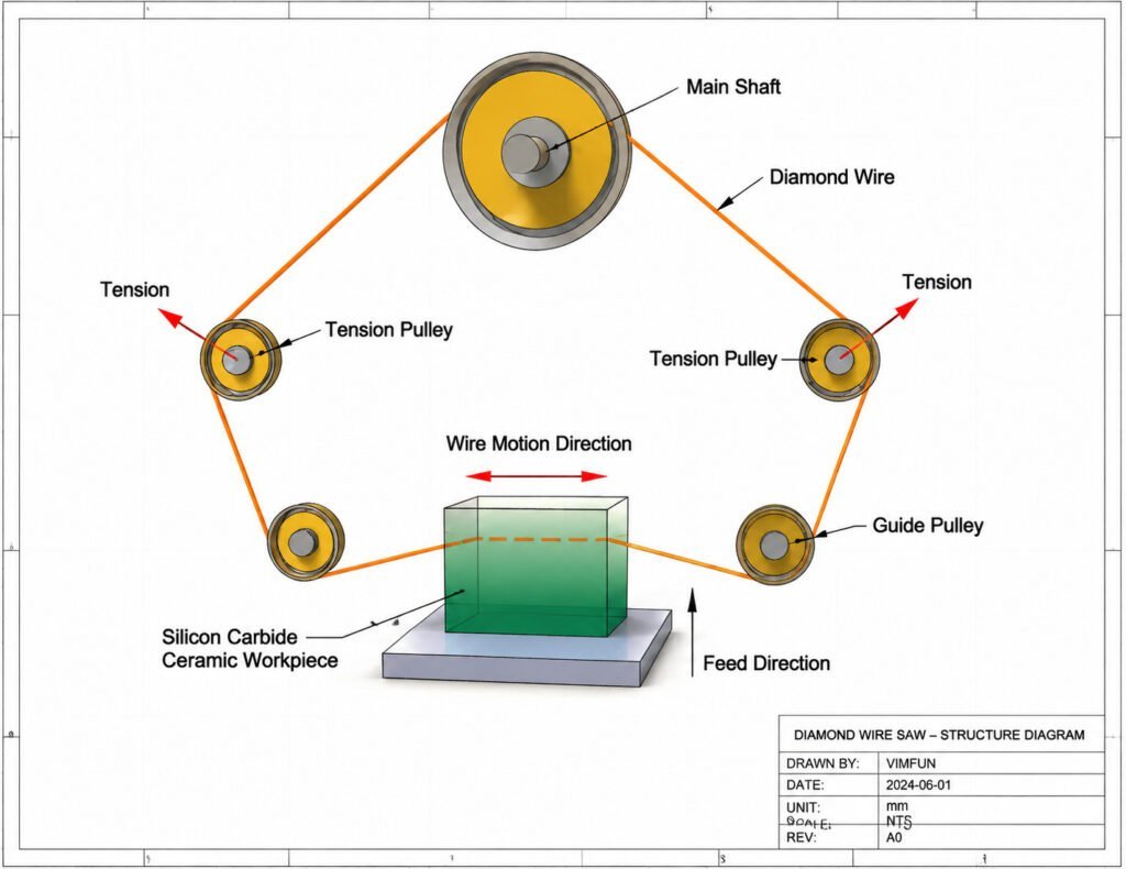
Diamond wire saw passes a continuously moving wire coated with fine diamond abrasive through the ZnS blank. The cutting zone is narrow — typically 0.25–0.45 mm wire diameter — and the wire makes distributed, low-force contact with the material. This produces a low kerf loss, a consistent cut surface, and minimal edge loading at the blank perimeter.
Inner diameter saw uses a rotating blade with diamond abrasive on its inner edge. The blade contacts the material in a single cutting arc. ID saws can achieve high dimensional accuracy on individual cuts, but the blade’s contact geometry applies localized force at the cut entry and exit points — where ZnS edge chipping risk is highest.
| Parameter | Diamond Wire Saw | ID Saw |
|---|---|---|
| Kerf width | 0.25–0.45 mm | 0.3–0.6 mm |
| Edge chipping risk | Low | Moderate |
| Surface Ra after cutting | 0.6–1.2 μm | 0.8–2.0 μm |
| TTV (Φ50 mm blank) | 8–15 μm | 10–25 μm |
| Multi-piece throughput | High (multi-wire) | One cut per cycle |
| Suitability for thin blanks | High | Moderate |
The kerf loss difference has a direct economic impact with high-value ZnS material. The analysis of kerf loss in optical cutting covers how kerf width translates into material yield across a production run — a consideration that applies to ZnS as it does to other infrared optical materials where raw material cost is significant.
A detailed technical comparison of wire saw and ID saw cutting in infrared optics production is covered in the wire saw vs ID saw analysis, which examines force profiles, surface output, and blank geometry across multiple material types.

Key Process Parameters for ZnS Cutting
Achieving the surface quality and dimensional consistency that ZnS polishing requires depends on controlling several process parameters that interact with the material’s grain-level behavior.
Wire tension and feed rate directly control the cutting force applied to the ZnS blank. Higher wire tension increases sawing rigidity but raises the force transmitted to the material at the cut entry point. For ZnS, feed rates are typically set conservatively to keep edge loading below the material’s local fracture threshold — a parameter that varies with ZnS grade, grain size, and blank geometry.
Coolant selection and flow manages two functions simultaneously: temperature control at the cutting zone and swarf removal from the cut surface. For ZnS, water-based coolants are standard. Oil-based coolants used in some metal cutting applications leave residue in ZnS grain boundary pores that complicates subsequent cleaning and can affect coating adhesion on finished optics. Coolant flow must be sufficient to continuously flush abrasive swarf from the cut — swarf redeposition on ZnS produces surface contamination that cannot be fully removed by post-cut cleaning.
Surface output targets for ZnS blanks leaving the cutting stage are typically Ra 0.6–1.2 μm on cut faces and TTV of 8–15 μm for blanks at Φ50 mm. These targets represent the entry condition for lapping and polishing; blanks arriving with rougher surfaces or higher TTV require additional lapping cycles to reach polishing-ready condition, adding process time and increasing the risk of edge chipping during the extended abrasive cycle.
Blank fixturing matters for ZnS more than for harder materials because ZnS deforms slightly under clamping pressure if fixturing is not designed for its stiffness and hardness range. Poorly distributed clamping forces introduce bow into the blank that cannot be distinguished from cutting-induced bow until the blank is released — at which point the geometry may be outside tolerance.
Selecting the Right ZnS Optics Cutting Machine for Your Application
The right ZnS optics cutting machine for a given application depends on the combination of blank geometry, production volume, material grade, and downstream tolerance requirements.
For thin blanks and wafer-form substrates (below 3 mm final thickness), diamond wire saws are generally preferred. The low cutting force and narrow kerf reduce the risk of blank fracture during cutting and minimize material loss from a substrate that has little allowance to spare. Multi-wire configurations allow multiple blanks to be cut simultaneously from a single boule section, improving throughput without proportionally increasing cutting time.
For thicker blanks and windows (above 5 mm) where throughput is prioritized, ID saws remain viable if edge quality is managed through blade selection, feed control, and entry/exit support. Edge support fixtures that back the ZnS at the blade exit point significantly reduce exit chipping — the most common quality issue with ID saw cutting of brittle optical materials.
For multispectral CVD ZnS (the higher-purity grade with visible-through-LWIR transmission), the tighter grain structure and higher material cost both support the choice of wire cutting over ID sawing. The narrower kerf recovers more usable substrate area per boule, and the lower cutting force reduces the risk of the subsurface damage that would be revealed during the extended polishing sequence that multispectral ZnS requires.
ZnS optics cutting machine selection also connects to downstream equipment planning. The infrared optics manufacturing equipment resource covers the full equipment sequence from cutting through polishing and coating for infrared optical materials — including how cutting machine output specifications flow into lapping and polishing equipment requirements.
For a broader view of how ZnS cutting fits within the IR optics manufacturing workflow alongside germanium and other infrared materials, the germanium IR optics manufacturing guide provides a comparative reference on equipment selection across the IR optical materials family.
Getting the Right Cut for ZnS Production
ZnS optics cutting machine selection is not a standalone decision — it connects directly to the surface quality and dimensional tolerances that the rest of the production line is designed to receive. A cutting process that delivers Ra 0.6–1.2 μm and TTV within 15 μm enables a lapping-to-polishing workflow that runs within its design parameters. A cutting process that delivers Ra 3+ μm or TTV above 30 μm forces the downstream process to absorb correction work it was not designed to handle, at the cost of additional cycle time, consumable use, and yield loss.
If you are specifying ZnS optics cutting equipment for a new production line, or evaluating whether your current process output is meeting the entry requirements for downstream operations, contact us to discuss machine configuration, process parameters, and the surface quality benchmarks relevant to your specific ZnS grade and blank geometry.