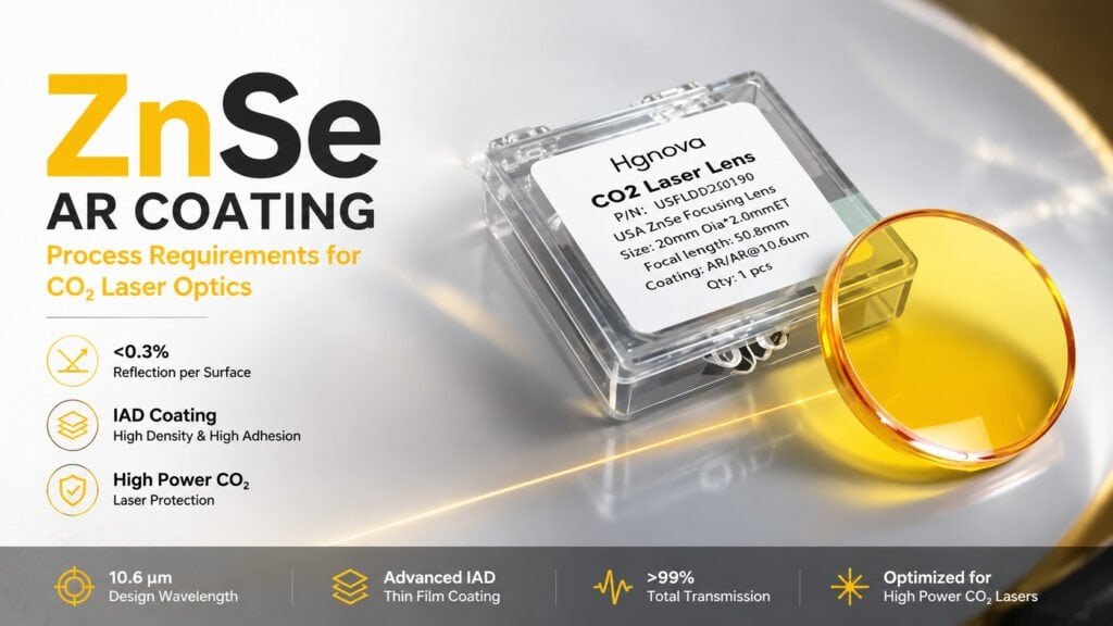
An uncoated ZnSe lens loses approximately 17% of incident light per surface to Fresnel reflection at 10.6 μm — the primary CO₂ laser wavelength. ZnSe AR coating reduces this loss to below 0.3% per surface, increasing transmitted power and protecting the lens from thermal damage caused by absorbed laser energy at the surface.
What Is ZnSe AR Coating?
ZnSe AR (anti-reflective) coating is a thin-film optical treatment applied to zinc selenide lens and window surfaces to minimize reflection losses at specific infrared wavelengths — most commonly 10.6 μm for CO₂ laser applications. The coating consists of one or more thin dielectric layers deposited under vacuum, engineered to cause destructive interference of reflected light and constructive interference of transmitted light.
Without ZnSe AR coating, zinc selenide’s high refractive index (n ≈ 2.40 at 10.6 μm) creates significant reflection at each optical surface — 17.2% per surface by Fresnel calculation. A two-surface ZnSe focus lens transmits only about 69% of incident light if left uncoated. With a properly designed single-wavelength AR coating, per-surface reflectance drops to below 0.3%, and total two-surface transmission exceeds 99%.
For high-power CO₂ laser cutting systems operating at 3–6 kW, the difference between coated and uncoated optics is not just efficiency — it is the difference between a lens that survives continuous operation and one that fractures from absorbed heat within minutes.
Why ZnSe Optics Require Anti-Reflective Coating
Reflection Loss at 10.6 μm
The Fresnel reflection at a ZnSe surface follows directly from its refractive index:
R = ((n − 1) / (n + 1))² = ((2.40 − 1) / (2.40 + 1))² ≈ 17.2% per surface
For a focus lens in a 3 kW CO₂ laser cutting head, that 17% loss per surface represents real power diverted away from the workpiece:
| Surface | Incident Power | Reflected | Transmitted |
|---|---|---|---|
| Front surface (uncoated) | 3,000 W | 516 W | 2,484 W |
| Rear surface (uncoated) | 2,484 W | 427 W | 2,057 W |
| Total transmitted (uncoated) | — | 943 W lost | 2,057 W (69%) |
| Total transmitted (AR coated) | — | ~30 W lost | ~2,970 W (>99%) |
That 943 W difference in transmitted power is not simply lost — it reflects back toward the laser source, heats the optical housing, and concentrates stress at the lens surfaces.
Thermal Damage Without Coating
ZnSe has extremely low bulk absorption at 10.6 μm — approximately 0.0005 cm⁻¹ in optical-grade material — which is precisely why it is the dominant material for high-power CO₂ laser optics. However, surface absorption is a different problem. Even a thin contamination layer, polishing residue, or surface micro-crack on an uncoated ZnSe lens can absorb enough laser energy to initiate thermal runaway: absorption raises local temperature, elevated temperature increases absorption coefficient, and the process accelerates until the lens fractures or the coating delaminates.
ZnSe AR coating reduces surface reflection to near zero, which eliminates the constructive interference pattern (standing wave) that concentrates optical energy at the lens surface in high-power beams. According to Coherent, properly AR-coated ZnSe optics with clean, defect-free surfaces are rated for continuous-wave CO₂ power densities well above 1 kW/cm² in production cutting and welding applications.
ZnSe AR Coating Process Requirements
Surface Quality Before Coating
ZnSe AR coating conformally covers the substrate — it cannot smooth or correct surface defects. Every scratch, residual polishing mark, and surface irregularity present before coating will remain present under the coating, creating local stress concentrations and adhesion failure points when the lens is operated under laser power. The substrate must meet these specifications before entering the coating chamber:
| Parameter | Required Specification | Why It Matters |
|---|---|---|
| Surface roughness (Ra) | < 1.0 nm | Roughness scatters deposited coating, reducing density |
| Scratch-Dig (MIL-PRF-13830B) | 60-40 minimum; 40-20 preferred | Scratches initiate local adhesion failure under laser power |
| Flatness (windows) | λ/4 or better | Coating follows substrate figure — cannot correct it |
| Subsurface damage | None (confirmed by etching) | Micro-cracks propagate under thermal cycling |
| Cleanliness | Free of organics and particles | Contamination causes pinholes and delamination |
Achieving Ra < 1 nm requires a dedicated polishing stage using chemo-mechanical polishing (CMP) on a pitch lap — the same process used in the ZnSe optics polishing step for IR optics production. The quality of upstream cutting and grinding directly determines how much polishing time is needed to reach coating-ready surface conditions.
Coating Methods Compared
| Method | Coating Density | Adhesion | Throughput | Best For |
|---|---|---|---|---|
| Ion-Assisted Deposition (IAD) | High | Excellent | Medium | High-power laser optics |
| E-beam evaporation (no IAD) | Medium | Good | High | Moderate-power applications |
| Magnetron sputtering | Very high | Excellent | Low | Research / specialty coatings |
| Ion-beam sputtering (IBS) | Very high | Excellent | Very low | Ultra-precision, low-scatter coatings |
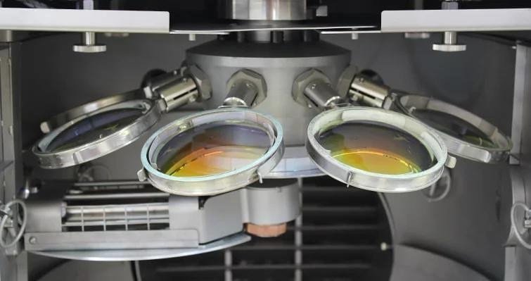
Ion-Assisted Deposition (IAD) is the production standard for ZnSe AR coatings used in CO₂ laser cutting heads. An electron beam evaporates the coating material while a separate ion source simultaneously bombards the growing film. The ion bombardment compacts the coating layer, increasing film density, improving adhesion to the ZnSe substrate, and reducing moisture uptake that would otherwise shift the coating’s peak performance wavelength over time.
For ZnSe CO₂ laser optics manufacturing at production volumes, IAD is the standard because the resulting coatings maintain their specified performance over thousands of laser hours without the wavelength drift seen in less dense coatings.
Coating Materials for ZnSe at 10.6 μm
Single-layer AR coatings for ZnSe at 10.6 μm require a material with low refractive index and good adhesion to ZnSe:
- YF₃ (yttrium fluoride) — n ≈ 1.35 at 10.6 μm, non-radioactive, current industry preference
- ThF₄ (thorium fluoride) — historically common, excellent optical properties, now regulated due to thorium radioactivity
- ZnS (zinc sulfide) — refractive index n ≈ 2.2 at 10.6 μm, used as the high-index layer in multilayer ZnSe AR coating designs
Modern broadband ZnSe AR coatings for systems operating across multiple CO₂ emission lines (9.3 μm and 10.6 μm) use multilayer designs with 3–7 alternating high- and low-index layers, achieving average reflectance below 1.5% across the full design band.
ZnSe AR Coating Specifications by Application
| Application | Wavelength | Target R (per surface) | Power Level |
|---|---|---|---|
| CO₂ cutting head (single line) | 10.6 μm | < 0.3% | 1–6 kW |
| CO₂ marking / engraving | 10.6 μm | < 0.5% | 20–150 W |
| Multi-line CO₂ broadband | 9.2–11.4 μm | < 1.5% avg | Multi-kW |
| LWIR thermal imaging window | 8–12 μm | < 1% avg | Passive |
| CO₂ spectroscopy cell | 8–14 μm | < 0.5% | Low power |
High-power CO₂ cutting applications drive the most demanding ZnSe AR coating requirements. Suppliers such as Edmund Optics catalog ZnSe optics with standard 10.6 μm single-band AR coatings as stock items, but production-volume cutting facilities typically specify custom coatings optimized for their exact operating wavelength and power density.
Common ZnSe AR Coating Problems
1. Coating Delamination After Initial Laser Use
Symptom: visible peeling or flaking at the lens surface, typically appearing within minutes to hours of first operation under laser power.
Cause: residual contamination on the ZnSe substrate before coating. Even sub-monolayer organic contamination (fingerprint oils, solvent vapor residue, vacuum grease migration) prevents proper adhesion between the coating and the ZnSe surface. The absorbed laser power then causes differential thermal expansion between the contaminated interface and the overlying coating film, and the coating separates.
Fix: validate the cleaning protocol — UV-ozone or plasma cleaning immediately before loading into the coating chamber, confirmed by contact angle measurement (< 5° for a clean ZnSe surface). Do not touch cleaned optics without clean-room gloves.
2. Wavelength Shift in Coating Performance
Symptom: measured reflectance at 10.6 μm is 3–5× higher than specified, but the reflectance minimum is at a nearby wavelength (10.3 or 10.9 μm instead of 10.6 μm).
Cause: coating thickness error during deposition, or porous coating absorbing atmospheric moisture after removal from the vacuum chamber. Moisture increases the effective optical thickness of low-density coating layers, which shifts the destructive interference minimum to longer wavelengths.
Fix: use IAD to maximize coating density and minimize moisture uptake. Implement in-situ optical monitoring during deposition to control layer thickness in real time. Store finished optics in dry nitrogen or silica gel environments.
3. Low Transmission Despite Low Reflectance
Symptom: a coated ZnSe lens measures low reflectance when tested with a spectrophotometer, but transmits less laser power than expected during use.
Cause: residual surface roughness above the coating’s capability to compensate. The ZnSe AR coating reduces specular reflection but cannot planarize micro-roughness — energy scattered by subsurface irregularities exits the beam path and never reaches the workpiece. This problem traces directly back to the ZnSe polishing stage not achieving Ra < 1 nm.
Fix: return the blank to polishing and verify Ra < 0.8 nm using a white-light interferometer before re-coating. Contact profilometers alone may miss the spatial frequencies most responsible for scatter at 10.6 μm.
ZnSe AR Coating in the Complete Production Workflow
ZnSe AR coating is the final optical process in a production chain that begins at the blank cutting stage. The quality of every preceding step determines whether the substrate meets coating requirements — and whether coated lenses survive long-term operation under laser power.
| Stage | Equipment | Output Specification |
|---|---|---|
| 1. Blank cutting | ZnSe lens cutting machine | Ra 0.5–1.5 μm, minimal edge chipping |
| 2. Centering | Centering machine | Round blank, ≤ 5 μm roundness |
| 3. Curve generation | Grinding machine | Correct radius, Ra 0.1–0.3 μm |
| 4. Polishing | CMP polishing machine | Ra < 1.0 nm, Scratch-Dig ≤ 60-40 |
| 5. Cleaning | UV-ozone / plasma | Contact angle < 5°, zero particulates |
| 6. AR coating | IAD coater | R < 0.3% at 10.6 μm per surface |
For manufacturers setting up ZnSe optics production lines — from cutting through to coating-ready substrates — see the infrared optics manufacturing equipment guide for equipment selection across all process stages.
If you are evaluating cutting and polishing equipment that delivers consistent coating-ready ZnSe substrates, contact us at daria@endlesswiresaw.com to discuss process parameters and equipment specifications for your production volume and quality targets.