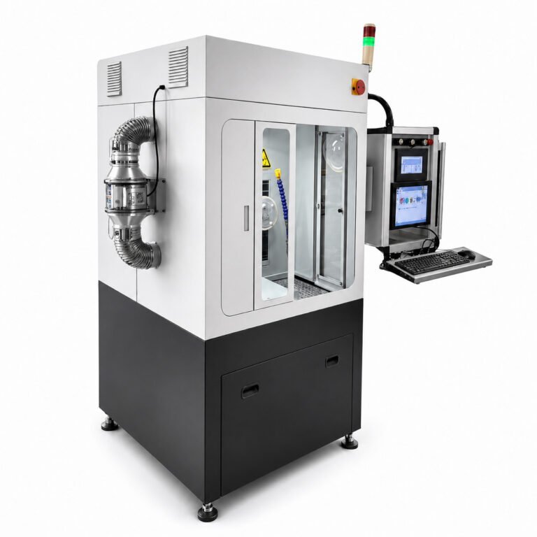
Producing high‑performance optical lenses involves a series of tightly controlled steps—each contributing directly to final quality, yield, and consistency. Understanding the optical lens manufacturing process from raw material to finished product helps engineers optimize workflow, reduce scrap, and improve product performance.

In this article, we’ll walk through the complete process, outline key technical challenges, compare how cutting plays different roles in glass versus plastic, and explain why certain errors introduced during cutting cannot be corrected later.
For a general overview of optical lens fabrication methods, see this Encyclopaedia Britannica resource on lens manufacturing:
https://www.britannica.com/technology/lens-optics/Manufacturing-optical-lenses
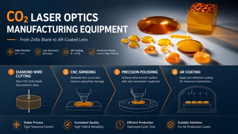
From Raw Material to Finished Lens: 7‑Step Process (Text Flow Diagram)
Below is a linear “diagram” of the optical lens manufacturing process in text format:
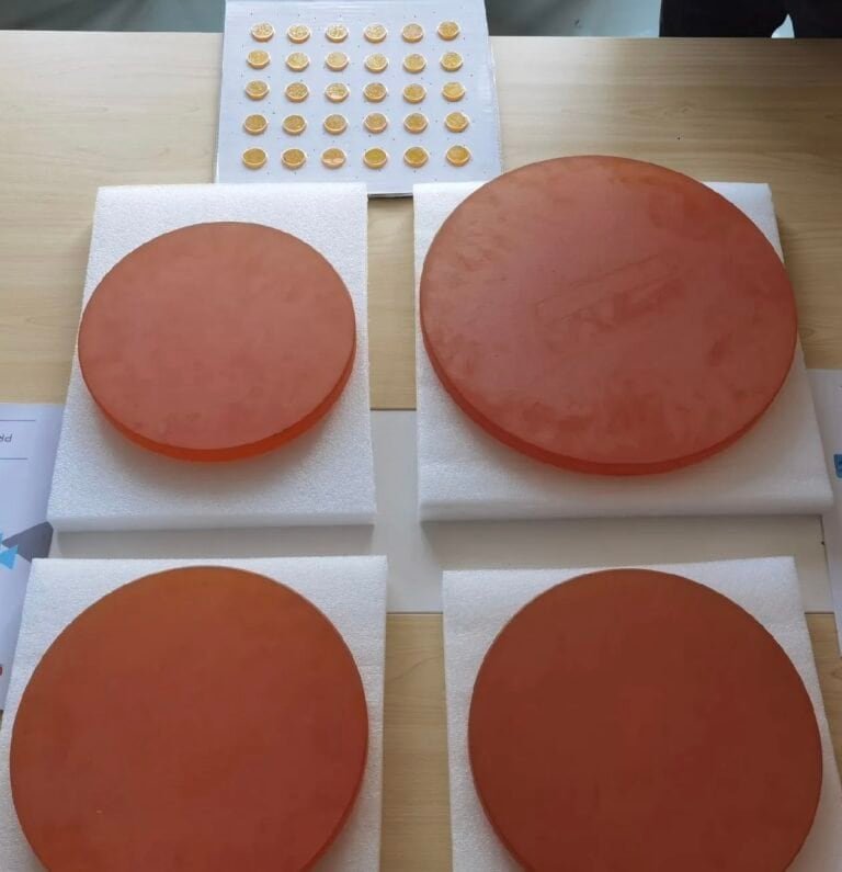
- Material Selection & Inspection ← Raw optical glass or polymer blank
- Blank Generation & Pre‑Forming ← Rough shaping to near net profile
- Precision Cutting & Contour Establishment ← [Cutting]
- Grinding & Sizing ← Oberflächenfigur und Dickenkontrolle
- Polieren ← Erforderliche Oberflächengüte und optische Qualität erzielen
- Beschichtungs- & Funktionsschichtauftrag ← AR-Beschichtungen, Filter
- Endkontrolle & Qualitätssicherung ← Interferometrie, MTF-Tests
Jeder dieser Schritte baut auf dem vorherigen auf. Fehler addieren sich statt sich aufzuheben, daher ist eine solide Basis – insbesondere ab Schritt 3 – entscheidend.
Stufenweise technische Herausforderungen
1. Material Selection & Inspection
- Technische Herausforderungen: Kontrolle der Brechungsindexhomogenität, Doppelbrechung, innerer Spannungen, Einschlüsse.
- Unvollkommenheiten in diesem Stadium begrenzen die erreichbare Oberflächenqualität unabhängig von nachfolgenden Bemühungen.
2. Blank Generation & Pre‑Forming
- Grobes Formen reduziert das Materialvolumen, kann aber Spannungen unter der Oberfläche einführen.
- Sorgfältiges thermisches Management und Spannungsmanagement sind erforderlich, um Rissbildung zu vermeiden.
3. Precision Cutting & Contour Establishment
- Das Schneiden definiert die äußere Kontur und die Materialbasis für alle nachfolgenden Operationen.
- Erfordert hohe geometrische Genauigkeit, stabile Spannvorrichtungen und geringe induzierte Spannungen.
- Errors here (eccentricity, tilt, uneven stock) cannot be fully corrected in grinding/polishing.
4. Grinding & Sizing
- This step removes material to approach final curvature and thickness.
- Challenges include tool wear, wheel loading, heat management, and maintaining consistent stock removal.
5. Polieren
- Polishing eliminates micro‑roughness and achieves optical surface quality.
- Sensitive to subsurface damage; polishing cannot “heal” cracks or deep fractures.
6. Coating
- Multilayer dielectric and AR coatings require surface cleanliness and stable substrate.
- Coating adhesion and uniformity depend on preceding surface quality.
7. Abschließende Inspektion
- Uses interferometry, modulation transfer function (MTF) testing, and other metrology tools.
- Confirms conformity to design, but cannot correct inherent flaws.
The Role of Cutting in Different Materials
Cutting in Glass Optics
Glass lenses (e.g., borosilicate, crown/flint types) are brittle and prone to micro‑fracture. Cutting must minimize:
- Surface cracks
- Subsurface damage
- Edge chipping
Typical strategies include diamond‑tool cutting and controlled feed rates to reduce fracture propagation.
Cutting in Plastic Optics
Plastic lenses (e.g., PMMA, PC) are more ductile than glass.
- Cutting can introduce heat softening, melting, or edge roll‑over if thermal build‑up is poorly managed.
- Coolants and low‑heat tool paths help preserve geometric accuracy.
Despite differences in material response, both require cutting to produce stable baselines for grinding.
Why Cutting Errors Cannot Be Fixed Later
Certain problems that originate during the cutting stage are fundamentally unrecoverable in subsequent processing:
1. Baseline Geometric Error
If the contour or stock distribution is uneven, grinding and polishing consume additional material to compensate, reducing yield and potentially exceeding tolerances.
2. Subsurface Cracks and Fractures
Subsurface damage reduces mechanical integrity. Polishing may remove superficial roughness but cannot eliminate cracks that extend below the surface layer.
3. Residual Stress
Improper cutting strategies can leave residual stresses that later warp during polishing or coating, affecting curvature stability.
4. Material Removal Asymmetry
Uneven starting stock makes symmetrical shaping difficult; downstream processes amplify these asymmetries in final optical performance.
In short: once inaccurate geometry or internal damage exists, no downstream step can fully correct it without significant yield loss or rework.
Abschluss
A robust optical lens manufacturing process depends on precision at every stage, but none more so than cutting. From establishing geometric baselines to controlling induced stress, cutting determines both manufacturing yield and the potential for achieving final optical specifications.
By understanding how each stage contributes—especially how cutting errors propagate downstream—engineers can design more resilient workflows and reduce defect rates in high‑precision optical products.