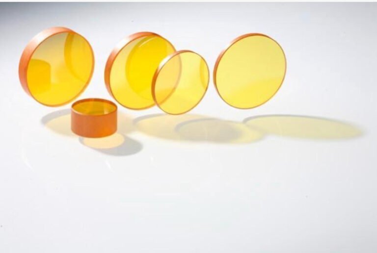
Zinc selenide optics polishing is the final surface finishing step that transforms a ground ZnSe blank into a functional infrared optical element. Because ZnSe is exceptionally soft (Knoop hardness ~120) and contains toxic selenium, polishing this material demands different techniques, slower removal rates, and stricter safety controls than polishing harder IR materials like germanium.
This guide covers the complete zinc selenide optics polishing workflow — from pre-polishing preparation through final surface inspection — with practical parameters for achieving laser-grade surface quality on CO₂ laser lenses, windows, and beam-splitter substrates.

What Is Zinc Selenide Optics Polishing?
Zinc selenide optics polishing is a controlled material removal process that reduces surface roughness from the ground state (typically Ra 0.3–0.8 μm after fine grinding) down to Ra ≤ 5 nm, while maintaining flatness and transmitted wavefront quality required for infrared optical applications. The process relies on a combination of chemical softening and mechanical abrasion — commonly called chemical-mechanical polishing (CMP) — to achieve scratch-free, subsurface-damage-free surfaces on ZnSe components.
ZnSe is the dominant lens material for high-power CO₂ laser systems operating at 10.6 μm wavelength due to its broad infrared transmission range (0.6–21 μm) and low absorption coefficient. However, its softness and brittleness make it one of the most challenging IR materials to polish. Even minor process deviations can introduce orange peel texture, subsurface fractures, or edge chipping that degrades laser transmission and shortens component life.
Key Parameters for Zinc Selenide Optics Polishing
Achieving consistent results requires tight control of multiple process variables. The table below summarizes practical parameter ranges for single-sided pitch polishing of ZnSe lenses and windows.
| Parameter | Recommended Range | Notes |
|---|---|---|
| Polishing pad | Optical-grade pitch (Gugolz 73 or equivalent) | Pitch conforms to surface shape; synthetic pads risk scratching |
| Abrasive type | Alumina (Al₂O₃) or colloidal silica | Alumina for stock removal; colloidal silica for final polish |
| Abrasive particle size | 0.05–1.0 μm | Start with 1.0 μm, step down to 0.05 μm for final stage |
| Slurry pH | 9.0–10.5 (mildly alkaline) | Alkaline environment provides chemical assist on ZnSe surface |
| Polishing pressure | 2–5 kPa (0.3–0.7 psi) | Lower than germanium due to ZnSe softness; excess pressure causes subsurface damage |
| Spindle speed | 20–60 RPM | Lower speeds reduce heat buildup and fracture risk |
| Material removal rate | 0.5–2.0 μm/min | Slower than germanium (~3–5 μm/min) to avoid damage |
| Target surface roughness | Ra ≤ 5 nm (laser-grade) | Measured by white-light interferometry |
| Target surface quality | 40-20 or better (scratch-dig) | Per MIL-PRF-13830B or ISO 10110-7 |
| Environment | Class 1000 cleanroom or better | Selenium dust containment + particle control |
Critical note: ZnSe polishing pressure should be 40–60% lower than the pressure used for germanium optics pohttps://www.opticalcutting.com/optics-polishing-machine/lishing. Applying germanium-level pressure to ZnSe is one of the most common causes of subsurface damage and orange peel defects.
How to Polish Zinc Selenide Optics: Step-by-Step Process
The zinc selenide optics polishing workflow follows a multi-stage sequence. Each stage progressively reduces surface roughness while minimizing subsurface damage accumulation.

Step 1: Pre-Polish Inspection and Preparation
Before polishing begins, inspect the ground ZnSe blank for edge chips, cracks, or deep grinding scratches. Measure incoming surface roughness (typically Ra 0.3–0.8 μm after fine lens grinding) and flatness using a profilometer.
Clean the workpiece with isopropyl alcohol and lint-free wipes in a fume hood. ZnSe blanks arriving from the cutting stage may carry residual coolant or particulates that contaminate the polishing slurry.
Mount the ZnSe blank onto the polishing fixture using optical wax or a vacuum chuck. Ensure even contact across the entire surface — uneven mounting creates wedge error during polishing.
Step 2: Rough Polishing (Stock Removal)
Apply alumina slurry (0.5–1.0 μm particle size) to a conditioned pitch lap. Set spindle speed to 30–50 RPM and polishing pressure to 3–5 kPa.
This stage removes the subsurface damage layer left by grinding — typically 5–15 μm deep in ZnSe. Target removal of 15–25 μm total material to ensure all grinding damage is eliminated.
Monitor surface appearance every 10–15 minutes. ZnSe surfaces transition from matte (ground) to semi-reflective as roughness decreases. Stop rough polishing when surface roughness reaches Ra 20–50 nm.
Step 3: Fine Polishing (Surface Finishing)
Switch to colloidal silica slurry (0.05–0.3 μm particle size) with pH adjusted to 9.5–10.5. Reduce polishing pressure to 2–3 kPa and spindle speed to 20–40 RPM.
The alkaline slurry chemically softens the ZnSe surface layer, enabling the fine abrasive particles to remove material with minimal mechanical force. This chemical-mechanical action is critical for achieving scratch-free surfaces on soft II-VI compound materials.
Continue fine polishing until surface roughness reaches Ra ≤ 5 nm and scratch-dig meets specification (typically 40-20 or 20-10 for high-power laser applications).
Step 4: Post-Polish Cleaning and Inspection
Remove the polished ZnSe optic from the fixture carefully — thermal shock or mechanical impact can induce micro-fractures at this stage.
Clean using a multi-step solvent rinse (acetone → isopropyl alcohol → deionized water) in a cleanroom environment. All cleaning must occur in a ventilated enclosure due to selenium residue on surfaces.
Perform final inspection:
- Surface roughness: White-light interferometry (Ra ≤ 5 nm)
- Surface quality: Nomarski DIC microscopy (scratch-dig evaluation)
- Transmitted wavefront: Interferometric testing at 10.6 μm or 632.8 nm
- Subsurface damage: Cross-polarization inspection for residual stress

Zinc Selenide Optics Polishing: Common Defects and Solutions
Even experienced optics shops encounter these recurring issues when polishing ZnSe. The key is recognizing the root cause early — before scrapping expensive blanks.
Orange Peel Texture After Polishing — What Causes It?
Orange peel is a micro-waviness pattern visible under reflected light, caused by differential material removal across ZnSe grain boundaries. Polycrystalline CVD-grown ZnSe is particularly susceptible because adjacent grains have different crystallographic orientations, leading to orientation-dependent polish rates.
Solutions:
- Reduce polishing pressure to ≤ 3 kPa
- Use finer abrasive (switch to 0.05 μm colloidal silica earlier)
- Extend fine polishing time with alkaline slurry to equalize removal rates
- Verify pitch lap conditioning — an unevenly conditioned lap amplifies grain-boundary effects
Subsurface Damage Not Fully Removed — How to Verify?
Subsurface damage (SSD) from prior grinding stages may persist below a visually smooth surface. If the polished ZnSe element is coated and installed in a high-power CO₂ laser, subsurface fractures can cause localized absorption, thermal lensing, and eventual coating failure.
Solutions:
- Ensure rough polishing removes at least 2–3× the expected SSD depth (for ZnSe after grinding, SSD depth is typically 5–15 μm)
- Use cross-polarization inspection to detect residual stress patterns
- When in doubt, extend rough polishing by 10 μm of additional material removal
Edge Chipping During Polishing — How to Prevent?
ZnSe edges are fragile due to low fracture toughness (~0.5 MPa·m^½). Chips propagate inward and contaminate the polishing surface with debris.
Solutions:
- Apply a protective chamfer (0.3–0.5 mm × 45°) before polishing begins
- Use lower polishing pressure near edges
- Ensure the polishing fixture provides full support — overhanging edges are at highest risk
Zinc Selenide Optics Polishing vs Germanium: How Polishing Differs
Both ZnSe and germanium are core materials for infrared optics manufacturing equipment, but their polishing processes differ significantly due to material property gaps.
| Factor | ZnSe Polishing | Germanium Polishing |
|---|---|---|
| Hardness (Knoop) | ~120 (very soft) | ~780 (moderately hard) |
| Fracture toughness | ~0.5 MPa·m^½ (brittle) | ~0.6 MPa·m^½ (slightly tougher) |
| Typical polishing pressure | 2–5 kPa | 5–12 kPa |
| Material removal rate | 0.5–2.0 μm/min | 3–5 μm/min |
| Primary defect risk | Orange peel, subsurface damage | Surface scratches, edge chips |
| Polishing pad | Pitch (preferred) | Pitch or polyurethane |
| Chemical assist | Alkaline slurry (pH 9–10.5) | Mild alkaline or neutral |
| Toxicity concern | High (selenium is toxic) | Low (germanium is relatively safe) |
| Cleanroom requirement | Mandatory (dust containment) | Recommended but less critical |
| Cost sensitivity | High (blanks are expensive, low rework tolerance) | High (germanium also expensive) |
The most important operational difference is pressure control. ZnSe’s extremely low hardness means that polishing parameters validated on germanium will almost certainly produce subsurface damage on ZnSe. Shops transitioning from germanium to ZnSe polishing should reduce pressure by at least 40% and expect 2–3× longer cycle times.
Selenium Safety in Zinc Selenide Optics Polishing
Selenium is a regulated toxic substance with an OSHA Permissible Exposure Limit (PEL) of 0.2 mg/m³ for airborne selenium compounds. During zinc selenide optics polishing, selenium-containing particles are generated in the polishing slurry and can become airborne during cleanup.
Required safety controls:
- Wet processing only: Never dry-polish ZnSe. Wet slurry traps selenium particles.
- Ventilated enclosure: All polishing equipment should operate within a ventilated enclosure with HEPA-filtered exhaust.
- PPE: Nitrile gloves, safety goggles, and N95 or P100 respirators during slurry handling and cleanup.
- Waste management: Selenium-containing slurry waste must be collected and disposed of as hazardous waste per local regulations.
- Air monitoring: Periodic air sampling near polishing stations to verify selenium levels remain below PEL.
Facilities that already handle ZnSe cutting with proper selenium safety protocols can typically extend the same controls to the polishing process. The polishing stage generates finer particles than cutting, so filtration effectiveness should be verified.
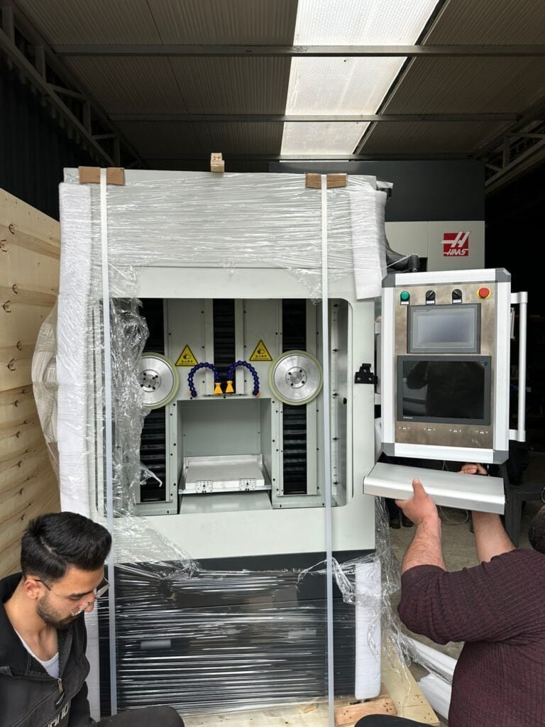
How Our Equipment Supports Zinc Selenide Optics Polishing
As an infrared optics equipment manufacturer, we design polishing systems specifically for soft, toxic II-VI compound materials like ZnSe. Our approach addresses the three core challenges — low hardness, grain-boundary effects, and selenium containment — through integrated machine design rather than aftermarket modifications.
Precision pressure control: Pneumatic load cells maintain polishing pressure within ±0.5 kPa across the entire workpiece surface, preventing the localized overload that causes subsurface damage and orange peel on ZnSe.
Enclosed slurry management: Sealed slurry circulation with inline filtration and HEPA-vented enclosure keep selenium exposure below regulatory limits without requiring separate containment infrastructure.
Multi-stage process automation: Programmable recipe control handles the transition from rough polishing (alumina) to fine polishing (colloidal silica) — including pressure, speed, and slurry changes — without operator intervention between stages.
Our polishing machines integrate with upstream ZnSe lens cutting equipment and double-sided lapping systems to form a complete ZnSe processing line from blank to finished optic.
Contact our engineering team to discuss your ZnSe polishing specifications and volume requirements.
Related ZnSe and IR Optics Resources
| Topic | Link |
|---|---|
| ZnSe Lens Cutting Machine — ZnSe Cluster Hub | ZnSe lens cutting machine |
| Infrared Optics Manufacturing Equipment — Pillar Page | Infrared optics manufacturing equipment |
| Germanium Optics Polishing Machine — Ge Polishing Reference | Germanium optics polishing machine |
| Germanium Lens Grinding Equipment — Pre-Polish Process | Germanium lens grinding equipment |
| Germanium Wafer Double-Sided Lapping — Lapping Reference | Wafer double-sided lapping |